seany65
Well-known
I apologise to the mods for what is basically a re-post of this, but I put the original in someone else's medis thread and it hasn't been answered so I thought it best to ask again separately:
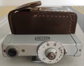
I've just received a Medis rangefinder which nominally only has a tiny screw missing, however the rangefinder was out vertically and horizontally by quite a way. I've adjusted it so the verticals line up using the screw on the distance dial, but I can't get the rangefinder's image down to the same level as the real image.
There is a little screw between the eyepiece and the distance dial but all that seems to do when turned quite a few turns to the left is almost stop the rangefinder image moving when turning the distance dial. I've turned it to the right enough to engage the distance dial properly again.
Am I right in thinking the screw between eyepiece and dial is the adjustment screw for high/low rangefinder images?
Here's a pic of my version. Click on thumb for big version:
Anyone got any idea what can be done if this screw isn't working properly?
Any help would be much appreciated.
__________________
Timmyjoe
Veteran
I am certainly no expert on rangefinders, but I do have a Saymont that I adjusted the vertical image (which is what I always believed was the up/down adjustment, so when the images are visually on top of each other, they are the same height and "line up"). On the Saymont, the end cap furthest from the viewing window is removed, and under that end cap are two screw heads, which you need to adjust very carefully, and very minimally, to bring the two image to be on top of one another. That's how you do it with a Saymont, not sure if a Medis works that way or not.
Best,
-Tim
Best,
-Tim
seany65
Well-known
Thanks for the reply Timmyjoe.
Your suggestion could explain why mine has a missing screw on the far end, and why I've seen one on ebay without that far end plate, although if correct I'd have no idea why they'd have an easily accessible screw that seems to disengage the distance wheel.
Anyway, here's the pic the seller (coloumbo321) took. Click on it to see it full size:
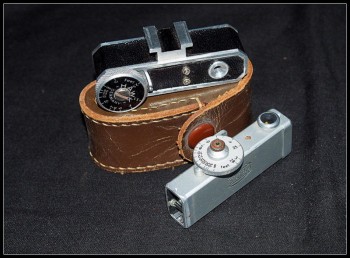
Copyright of the photo owned by 'columbo321', and used just for illustration purposes only.
Does the inside look anything like yours, Timmyjoe?
So either the medis can be adjusted using one or more screws inside at one end, or 1 or 2 people thought they could.
Being a bit of a clumsy clot I'll try and get further info on this.
Thsnks for your help Timmyjoe.
Your suggestion could explain why mine has a missing screw on the far end, and why I've seen one on ebay without that far end plate, although if correct I'd have no idea why they'd have an easily accessible screw that seems to disengage the distance wheel.
Anyway, here's the pic the seller (coloumbo321) took. Click on it to see it full size:
Copyright of the photo owned by 'columbo321', and used just for illustration purposes only.
Does the inside look anything like yours, Timmyjoe?
So either the medis can be adjusted using one or more screws inside at one end, or 1 or 2 people thought they could.
Being a bit of a clumsy clot I'll try and get further info on this.
Thsnks for your help Timmyjoe.
charjohncarter
Veteran
I have the Medis RF which is exactly like yours. I always thought that screw between the eyepiece and the dial was to lock the image so you could adjust the RF more easily. I maybe wrong but mine does the same as yours. Mine is missing the same screw on the cap end as yours????? And I have never had to try to fix the vertical alignment. By the way, once I adjusted the RF it has never needed re-adjustment for 10 years.
seany65
Well-known
Thanks for the new info charjohn.
You may well be right about the screw between the eyepiece and the dial being to disengage the dial to help in any horizontal adjustment.
I hope it ain't true though, as that means I may have to fiddle with tiny screws to adjust the verticals.
You may well be right about the screw between the eyepiece and the dial being to disengage the dial to help in any horizontal adjustment.
I hope it ain't true though, as that means I may have to fiddle with tiny screws to adjust the verticals.
seany65
Well-known
Well, I took the ruddy thing apart to see what I could do. Here's the pics and blurb:
As always, click on the thumbs for big versions.
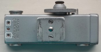
First the 'far side' end plate as that seemed to be the place to start:
I couldn't see anything to adjust.
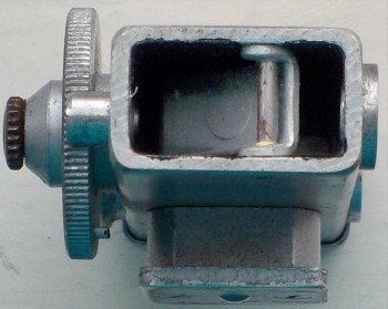
Now the near side. I took the end plate off and found 2 screws:
I looked inside and saw this:
A thing, which had the two screws sticking into it. I presumed these where adjusting screws.
I tried to turn them but neither would and I didn't want to risk damaging it.
Do these screws look like adjusting screws to anyone else, and if so, should they be very difficult to turn?
As always, click on the thumbs for big versions.
First the 'far side' end plate as that seemed to be the place to start:
I couldn't see anything to adjust.
Now the near side. I took the end plate off and found 2 screws:
I looked inside and saw this:
A thing, which had the two screws sticking into it. I presumed these where adjusting screws.
I tried to turn them but neither would and I didn't want to risk damaging it.
Do these screws look like adjusting screws to anyone else, and if so, should they be very difficult to turn?
charjohncarter
Veteran
Thanks, I haven't tried to see if my screws will work (move). But they look like the only thing that could be used to adjust vertical.
xayraa33
rangefinder user and fancier
I wonder if one RF adjustment is the rotation of the RF window itself, a wedge prism affair, like on a Barnack Leica?
Requin
Established
I own 2 different rangefinders which work on the same principle like your medis (I guess). Both allow a vertical adjustment with an adjustment screw but no horizontal alignment. If there is a distance fault you aim at a target at least 300m/1,000 feet away and adjust with the knurled little dial in the middle of the bigger dial.
Hope that helps.
Hope that helps.
seany65
Well-known
xayraa, Thanks for the suggestion but nope, I've just just tried and I can't get the eyepiece to rotate.
Requin, Thanks for trying to help, I've been able to adjust for the vertical alignment in the way you mention.
I've been looking at the black L-shaped thing in the medis. I get the impression that it is very slightly tilted downwards at the front compared to the back. If so, I think this is what's making the rf image a little higher than the real image, although I could be completely wrong on that.
I'll probably have to have another go at turning the 2 little screws...
and risk breaking the ruddy thing.
charjohncarter
Veteran
Careful, seany65. But let us know what happens.
xayraa33
rangefinder user and fancier
xayraa, Thanks for the suggestion but nope, I've just just tried and I can't get the eyepiece to rotate.
Requin, Thanks for trying to help, I've been able to adjust for the vertical alignment in the way you mention.
I've been looking at the black L-shaped thing in the medis. I get the impression that it is very slightly tilted downwards at the front compared to the back. If so, I think this is what's making the rf image a little higher than the real image, although I could be completely wrong on that.
I'll probably have to have another go at turning the 2 little screws...
and risk breaking the ruddy thing.
On the Barnacks it is not the eyepiece for vertical adjustment on the RF but the front window closest to the high shutter speed dial. One unscrews the chrome ring off and rotates the glass window ( prism) to get the correct vertical alignment.
But you said you got the vertical alignment right on so I suspect the Medis RF uses a different set-up.
seany65
Well-known
xayraa33, I see. rather like the fed 2 d4 that I have then.At least, as far as I can remember I had to fiddle with a little ring under the outer ring. I've just had a quick look and it doesn't look like either front ring can be removed.
charjohn, yup, carefully does it. Although with my track record it's more likely to be "careful still breaks the ruddy thing".
charjohn, yup, carefully does it. Although with my track record it's more likely to be "careful still breaks the ruddy thing".
seany65
Well-known
Well, I've had the near end-plate off again to see what I could do with those two little screws.
I managed to loosen them enough to move the black L-shaped bit, but all that did was move the RF image slightly from side to side.
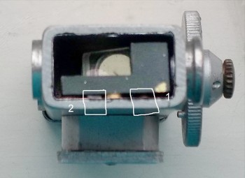
There is a screw in the long side of the L-shape and a hole in the body above so that a screwdriver can be put through to turn the screw in the L-shape.
If you look at the 3rd photo in the 6th post, you'll see a brass bit between the two numbered squares. This is the bit with the screw-head.
Once I'd loosened that as well, I could get the whole thing to tilt front to back as well as turn.
Unfortunately the precise fiddling necessary to align the horizontals and verticals was beyond my iq and patience.
At several points I couldn't even see the RF image.
I finally managed to get it back to what it had been before I fiddle with this end of of the ruddy thing.
So for me the end of fiddling has been reached. I'd rather return it and let someone else have a go.
I managed to loosen them enough to move the black L-shaped bit, but all that did was move the RF image slightly from side to side.
There is a screw in the long side of the L-shape and a hole in the body above so that a screwdriver can be put through to turn the screw in the L-shape.
If you look at the 3rd photo in the 6th post, you'll see a brass bit between the two numbered squares. This is the bit with the screw-head.
Once I'd loosened that as well, I could get the whole thing to tilt front to back as well as turn.
Unfortunately the precise fiddling necessary to align the horizontals and verticals was beyond my iq and patience.
At several points I couldn't even see the RF image.
I finally managed to get it back to what it had been before I fiddle with this end of of the ruddy thing.
So for me the end of fiddling has been reached. I'd rather return it and let someone else have a go.
Share:
-
This site uses cookies to help personalise content, tailor your experience and to keep you logged in if you register.
By continuing to use this site, you are consenting to our use of cookies.