rxmd
May contain traces of nut
How do etched framelines work so that the eye can keep them in focus, and how are they etched in general?
A 50mm frame or at least a horizontal line in would be a great thing in most FSU rangefinders, especially the Zorki-3 and -4... (and TTL metering, of course).
Philipp
A 50mm frame or at least a horizontal line in would be a great thing in most FSU rangefinders, especially the Zorki-3 and -4... (and TTL metering, of course).
Philipp
jlw
Rangefinder camera pedant
Getting them to be in focus is a matter of how the optics are designed.
If you've ever taken a regular optical viewfinder apart, you'll have noticed that it consists of a negative (diverging) lens in the front, and a positive (converging) lens in the back. The negative lens captures a virtual image that defines the view of the picture; the positive lens just makes it easier for the eye to focus on the virtual image, so the finder can be more compact. (It's possible to make a perfectly good viewfinder with only a front negative lens and a rear peepsight to align the eye, but the finder has to be several inches long in order to allow the eye to focus.)
Anyway, since the positive lens is basically a magnifying lens, you can see how by choosing a strong enough power for this lens, the designer can make it possible to focus the eye ON the surface of the front lens. Then, if lines are etched onto that lens, they'll be more or less in focus as you view through the finder.
I'm oversimplifying considerably here, but basically that's how it's done. If a finder has not already been designed with the proper negative and positive values, it would be difficult to re-engineer it after the fact.
Still, if you want to open up a viewfinder and give it a try, one reversible way to add the lines would be to use thin self-adhesive graphing strips, such as the Chartpak brand (once widely sold in art supply stores before computers took over the business of presentation graphics.)
Spyderman
Well-known
I think that in the Zorki 3 or 4 you won't be able to add lines. I was thinking about making a projected framelines, at least for 85mm lens.
That, and the TTL metering is going to be my summer project
rxmd
May contain traces of nut
jlw,
thanks for the explanation. (I guess this also explains how diopter correction works.) So basically I would have to find the focus point of the back lens and add a glass plate with some lines there (or just a crosshair) if it happens to be in free air, or hope that it falls on a lens surface and put some lines on this particular lens. I guess projected framelines would be easier to do as long as they don't have to be in focus, but then there's the problem of finding enough free space in the viewfinder.
Since we're at it anyway, another viewfinder marvel I've been wondering about is collimated rangefinders - I was wondering about why some rangefinder patches are sharply delimited while others aren't. Does this work similarly, i.e. the edge of the rangefinder patch simply being in focus?
Spyderman,
Philipp
thanks for the explanation. (I guess this also explains how diopter correction works.) So basically I would have to find the focus point of the back lens and add a glass plate with some lines there (or just a crosshair) if it happens to be in free air, or hope that it falls on a lens surface and put some lines on this particular lens. I guess projected framelines would be easier to do as long as they don't have to be in focus, but then there's the problem of finding enough free space in the viewfinder.
Since we're at it anyway, another viewfinder marvel I've been wondering about is collimated rangefinders - I was wondering about why some rangefinder patches are sharply delimited while others aren't. Does this work similarly, i.e. the edge of the rangefinder patch simply being in focus?
Spyderman,
The TTL meter from the Russian site I was linking to looks fairly simple. I assume since you're based in Slovakia you can read Russian (judging from how with my limited fluency in Russian and Ukrainian I could get along in Slovak somehow when I was hiking in the Tatras); if not, I could translate the instruction from that site into English if I find the spare time. I also have the schematics for Huw Finney's Leica III TTL meter, which is considerably different electronically (basically just a microcontroller); it should be simpler to build and adjust, because all the adjustment can be done in software, so you can correct for things like linearity which is difficult with the simple differential amplifier that the Russians are using. And it has the advantage that it reads off the curtain so it's easier to make it properly centerweighted.That, and the TTL metering is going to be my summer project
Philipp
Spyderman
Well-known
I am planning to use the circuit, but also to point the cell at the first curtain - as you suggest. I feel more comfortable with analog circuits
this microcontroller doesn't attract me at all 
I tried the idea of projected framelines with removed top, where I just placed a mirror between RF mirror and viewfinder, and the VF turned yellow, so with proper masking and shape of the mirror, I believe it is possible. Probably it won'tbe possible to make the lines complete (the bottom line), but at least the top, left and right...
Good luck rxmd.
jlw
Rangefinder camera pedant
rxmd said:So basically I would have to find the focus point of the back lens and add a glass plate with some lines there (or just a crosshair) if it happens to be in free air, or hope that it falls on a lens surface and put some lines on this particular lens.
Yes, basically that would be the principle. You'd have to hope that the best focus point fell at some accessible location. With the top cover removed from the camera, I suppose it would be fairly easy to take a small object such as a wire, and move it around in the optical path to see if you could find a location where it was reasonably in focus when the eye was viewing through the eyepiece.
Etching framelines doesn't add significantly to the cost of making a camera, so I have to assume that if it were easy, the original designers would have done it. Still, might be worth investigating, if only to gain a greater appreciation of the problems of camera design.
I guess projected framelines would be easier to do as long as they don't have to be in focus, but then there's the problem of finding enough free space in the viewfinder.
Yes, space would definitely be a problem -- I think some of the shutter-timing mechanism winds up being in the space where the projection optics would need to be. You'd still need to plan things so the framelines wound up in fairly good focus -- that type of viewfinder isn't of much use if they're not -- but at least there'd be the possibility of incorporating an auxiliary lens to bring them into focus, if there was room. I've seen this in some viewfinders: a rectangular positive lens for focusing the framelines, with a hole in the middle of it so the rangefinder image can pass through.
Since we're at it anyway, another viewfinder marvel I've been wondering about is collimated rangefinders - I was wondering about why some rangefinder patches are sharply delimited while others aren't. Does this work similarly, i.e. the edge of the rangefinder patch simply being in focus?
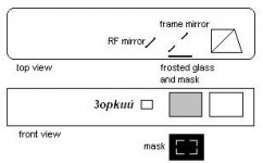
Yup, that's the basic principle. The rangefinder incorporates extra optics to form its virtual image at the plane of a mask, and then there are more optics on the other side to bring the edges of the mask into focus at the eyepiece.
Getting the rangefinder image, the mask, the framelines, the viewfinder image, and often a meter readout ALL come into focus at roughly the same distance, so the eye can see them all sharply, requires a rather complex optical system of positive lenses, negative lenses, mirrors, beamsplitters and masks -- all precisely adjustable and all packed in to a tiny space. This is the main reason a modern rangefinder camera is more expensive than an SLR with otherwise similar specifications!
Spyderman
Well-known
On a Zorki rangefinder there are only 2 mirrors: one behind the RF window, the other is in the middle of the viewfinder. No lenses. To add projected framelines to Zorki you need just a frosted glass in front (to let some light in), then a mirror with a hole in the middle to let the RF image through, and also the mask somewhere. I thought the mask could be right behind the frosted glass, in front of the mirror (just like it is on a Canonet)...
I attached a drawing how I want to do it...
Attachments
Last edited:
rxmd
May contain traces of nut
I guess the Zorki 5/6 with its diopter adjustment has a different setup, then, because it definitely has lenses. Your setup looks OK to me. How large is the beamsplitter? That seems to be the upper limit for the size of the framelines.
One issue is that it will be difficult to have a frameline at the bottom.
On the other hand, with your setup it will be easy to include the TTL meter readout. Just use the Russian circuit with a two-colour red/green LED and put it somewhere at the bottom of the frosted glass window, possibly in a corner. You get a lot of space to choose from.
Philipp
Spyderman
Well-known
I guess the Zorki 5/6 with its diopter adjustment has a different setup, then, because it definitely has lenses.
Also Zorki 4 has lenses, I just meant that there are no lenses in the RF part. All the diopter correction is done by just 2 lenses between eye and the glued prism.
jlw
Rangefinder camera pedant
Spyderman said:On a Zorki rangefinder there are only 2 mirrors: one behind the RF window, the other is in the middle of the viewfinder. No lenses. To add projected framelines to Zorki you need just a frosted glass in front (to let some light in), then a mirror with a hole in the middle to let the RF image through, and also the mask somewhere. I thought the mask could be right behind the frosted glass, in front of the mirror (just like it is on a Canonet)...
I attached a drawing how I want to do it...
Looks as if it should work in principle, if there's space mechanically in there. You might need to add a positive lens (with a hole in it for the RF image) between the frameline mirror and the beamsplitter to get the framelines in focus.
Most of the pieces you need probably could be pirated out of broken Japanese compact RF cameras with projected framelines.
This should be an interesting project for the determined Zorki "hot-rodders" out there...
vicmortelmans
Well-known
jlw said:You might need to add a positive lens (with a hole in it for the RF image)
lenses with holes. That's new. How would you do that? I think you can shape the borders of lens using a grinder, but cutting holes through it is a different thing.
Remark: I was buying a new pair of glasses the other day, and appearantly most lenses are plastic today. Only about 10% more expensive than glass. Wouldn't plastic be more easy to operate on than glass? Where could you buy standard lens elements for a reasonable price?
Groeten,
Vic
jlw
Rangefinder camera pedant
vicmortelmans said:lenses with holes. That's new. How would you do that? I think you can shape the borders of lens using a grinder, but cutting holes through it is a different thing.
I've seen a lot of "holey" lenses used inside the range/viewfinder optical systems of various rangefinder 35s. Undoubtedly the easiest way to get one would be to pilfer it out of a broken camera.
Plastic might be easier to shape, but I'm pretty sure you can grind a hole through glass if you have the appropriate abrasive and tool.
mac_wt
Cameras are like bunnies
Spyderman said:On a Zorki rangefinder there are only 2 mirrors: one behind the RF window, the other is in the middle of the viewfinder. No lenses. To add projected framelines to Zorki you need just a frosted glass in front (to let some light in), then a mirror with a hole in the middle to let the RF image through, and also the mask somewhere. I thought the mask could be right behind the frosted glass, in front of the mirror (just like it is on a Canonet)...
I attached a drawing how I want to do it...
If you want to go ahead with this project, you might try to cannibalize a Canonet 28. There are a lot of them around, and they can be had cheap. They contain frosted glass, lenses, mirror,...
Wim
Share:
-
This site uses cookies to help personalise content, tailor your experience and to keep you logged in if you register.
By continuing to use this site, you are consenting to our use of cookies.