DWH
Newbie
Gday all, first time I'm joining your forum.
Anyway I was talking to a fellow RF lover at work regards some mods I've done to rescue my GSN from the big RF heaven and he said you guys might be interested.
Like many others I picked up a Electro 35 in beautiful condition from an ebay auction for $20, to find after the first roll that the light meter was all over the place. After half a day of fault finding (being an engineer by trade this was kind of my area) I gave up on the number of dud and un-known components. I thought, stuff this, it would be easier to make my own electronics than try and fix this old analogue thing.
So, I did. For me, being use to SLRs, not having control over the shutter speed (or even knowing what it was going to be) was a killer. I figured I'd rather rely on an external light meter or the sunny 16 rule rather than have complete automation. Therefore I went down the more simple track of making a set of fully manual electronics for it.
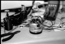
The electrical bit was really quite simple. Very few components using a standard modern PIC microcontroller. I've used loads of these before in a full range of designs and they've proven very reliable and flexible. The hard part came when I said to myself, "this thing has to still look like a 60's rangefinder." So the only visable alteration to the camera was to remake the front switch ring that originally held the bulb/auto/flash components to be a multi-position switch to select the shutter speed. I ended up with it being 11 position, this was just the maximum number of positions I could fit in with the physical constraints of the mechanism. These positions cover about 120 degrees of rotation of the front ring. While I can alter it at any time through software, I chose B, 2sec, 1sec, 1/2, 1/5, 1/10, 1/25, 1/50, 1/100, 1/250, 1/500 as my speeds.
All up, the modification of the switch mechanism (all physical, making PCB, cutting, etc.) took the best part of a week of evenings where as the rest of the electronics took about 1 day on the weekend. If anyone is interested in further info to perhaps repeat this for their own, let me know and I'll see what I can come up with.
Oh yes, the other requirement I placed on it was to get rid of most of the unreliable switches. Therefore all that's left is the top contactor on the shutter button, and the internal shutter released and flash sync switches. The rest of the electronics that I couldn't seem to get to work 100% of the time is completely redundant.
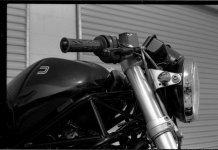
Attached is one pic while I was working on the electrics and a quick shot in the shed from the first test roll (focused with a tape measure because the rangefinder was still completely out of whack, since calibrated.)
Anyway I was talking to a fellow RF lover at work regards some mods I've done to rescue my GSN from the big RF heaven and he said you guys might be interested.
Like many others I picked up a Electro 35 in beautiful condition from an ebay auction for $20, to find after the first roll that the light meter was all over the place. After half a day of fault finding (being an engineer by trade this was kind of my area) I gave up on the number of dud and un-known components. I thought, stuff this, it would be easier to make my own electronics than try and fix this old analogue thing.
So, I did. For me, being use to SLRs, not having control over the shutter speed (or even knowing what it was going to be) was a killer. I figured I'd rather rely on an external light meter or the sunny 16 rule rather than have complete automation. Therefore I went down the more simple track of making a set of fully manual electronics for it.
The electrical bit was really quite simple. Very few components using a standard modern PIC microcontroller. I've used loads of these before in a full range of designs and they've proven very reliable and flexible. The hard part came when I said to myself, "this thing has to still look like a 60's rangefinder." So the only visable alteration to the camera was to remake the front switch ring that originally held the bulb/auto/flash components to be a multi-position switch to select the shutter speed. I ended up with it being 11 position, this was just the maximum number of positions I could fit in with the physical constraints of the mechanism. These positions cover about 120 degrees of rotation of the front ring. While I can alter it at any time through software, I chose B, 2sec, 1sec, 1/2, 1/5, 1/10, 1/25, 1/50, 1/100, 1/250, 1/500 as my speeds.
All up, the modification of the switch mechanism (all physical, making PCB, cutting, etc.) took the best part of a week of evenings where as the rest of the electronics took about 1 day on the weekend. If anyone is interested in further info to perhaps repeat this for their own, let me know and I'll see what I can come up with.
Oh yes, the other requirement I placed on it was to get rid of most of the unreliable switches. Therefore all that's left is the top contactor on the shutter button, and the internal shutter released and flash sync switches. The rest of the electronics that I couldn't seem to get to work 100% of the time is completely redundant.
Attached is one pic while I was working on the electrics and a quick shot in the shed from the first test roll (focused with a tape measure because the rangefinder was still completely out of whack, since calibrated.)
Attachments
btgc
Veteran
Holy Grain, this is crazy and still amazing ! Pretty sure I'm not only one who would like to read followup and see more pics from workshop and rebuilt '35.
whitecat
Lone Range(find)er
Will there be a Bride of Yashica Electro also?
NickTrop
Veteran
Incredible. The talent some people have is amazing
pesphoto
Veteran
So how much will you be charging for us to send you our Yashica's with broken down metering systems for conversion? You might have a few takers.
wallace
Well-known
This sounds great! I am sure that this is of big interest for many rff members (like me).
Hope to hear from you more in the future.
Nice monster, btw...
Wallace
Hope to hear from you more in the future.
Nice monster, btw...
Wallace
Peter_Jones
Well-known
Excellent work ") great to see a new lease of life in what would have been a scrap camera.
great to see a new lease of life in what would have been a scrap camera.
Welcome to the forum.
great to see a new lease of life in what would have been a scrap camera. Welcome to the forum.
KoNickon
Nick Merritt
Sounds neat! How about a picture of what the camera looks like now?
IK13
Established
My hat's off to you!
sol33
Established
Wow, thats really agreat idea! Using a PIC to control the camera opens a lot of interesting possibilities. Did you try to read the Lightmeter with the PIC? Apart from stuff like metering in manual mode or an aperture priority mode with exposure lock it might even be possible to implement something similiar to a TTL flash. (well, more of an ATL flash actually) I am really tempted to try this myself.
Please keep us up to date on your project, any information (a circuit diagram?) would be greatly appreciated!
Please keep us up to date on your project, any information (a circuit diagram?) would be greatly appreciated!
Share:
-
This site uses cookies to help personalise content, tailor your experience and to keep you logged in if you register.
By continuing to use this site, you are consenting to our use of cookies.