DWH
Newbie
Gday all, first time I'm joining your forum.
Anyway I was talking to a fellow RF lover at work regards some mods I've done to rescue my GSN from the big RF heaven and he said you guys might be interested.
Like many others I picked up a Electro 35 in beautiful condition from an ebay auction for $20, to find after the first roll that the light meter was all over the place. After half a day of fault finding (being an engineer by trade this was kind of my area) I gave up on the number of dud and un-known components. I thought, stuff this, it would be easier to make my own electronics than try and fix this old analogue thing.
So, I did. For me, being use to SLRs, not having control over the shutter speed (or even knowing what it was going to be) was a killer. I figured I'd rather rely on an external light meter or the sunny 16 rule rather than have complete automation. Therefore I went down the more simple track of making a set of fully manual electronics for it.
The electrical bit was really quite simple. Very few components using a standard modern PIC microcontroller. I've used loads of these before in a full range of designs and they've proven very reliable and flexible. The hard part came when I said to myself, "this thing has to still look like a 60's rangefinder." So the only visable alteration to the camera was to remake the front switch ring that originally held the bulb/auto/flash components to be a multi-position switch to select the shutter speed. I ended up with it being 11 position, this was just the maximum number of positions I could fit in with the physical constraints of the mechanism. These positions cover about 120 degrees of rotation of the front ring. While I can alter it at any time through software, I chose B, 2sec, 1sec, 1/2, 1/5, 1/10, 1/25, 1/50, 1/100, 1/250, 1/500 as my speeds.
All up, the modification of the switch mechanism (all physical, making PCB, cutting, etc.) took the best part of a week of evenings where as the rest of the electronics took about 1 day on the weekend. If anyone is interested in further info to perhaps repeat this for their own, let me know and I'll see what I can come up with.
Oh yes, the other requirement I placed on it was to get rid of most of the unreliable switches. Therefore all that's left is the top contactor on the shutter button, and the internal shutter released and flash sync switches. The rest of the electronics that I couldn't seem to get to work 100% of the time is completely redundant.
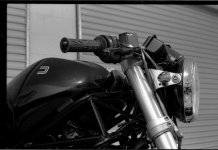
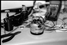
Attached is one pic while I was working on the electrics and a quick shot in the shed from the first test roll (focused with a tape measure because the rangefinder was still completely out of whack, since calibrated.)
Anyway I was talking to a fellow RF lover at work regards some mods I've done to rescue my GSN from the big RF heaven and he said you guys might be interested.
Like many others I picked up a Electro 35 in beautiful condition from an ebay auction for $20, to find after the first roll that the light meter was all over the place. After half a day of fault finding (being an engineer by trade this was kind of my area) I gave up on the number of dud and un-known components. I thought, stuff this, it would be easier to make my own electronics than try and fix this old analogue thing.
So, I did. For me, being use to SLRs, not having control over the shutter speed (or even knowing what it was going to be) was a killer. I figured I'd rather rely on an external light meter or the sunny 16 rule rather than have complete automation. Therefore I went down the more simple track of making a set of fully manual electronics for it.
The electrical bit was really quite simple. Very few components using a standard modern PIC microcontroller. I've used loads of these before in a full range of designs and they've proven very reliable and flexible. The hard part came when I said to myself, "this thing has to still look like a 60's rangefinder." So the only visable alteration to the camera was to remake the front switch ring that originally held the bulb/auto/flash components to be a multi-position switch to select the shutter speed. I ended up with it being 11 position, this was just the maximum number of positions I could fit in with the physical constraints of the mechanism. These positions cover about 120 degrees of rotation of the front ring. While I can alter it at any time through software, I chose B, 2sec, 1sec, 1/2, 1/5, 1/10, 1/25, 1/50, 1/100, 1/250, 1/500 as my speeds.
All up, the modification of the switch mechanism (all physical, making PCB, cutting, etc.) took the best part of a week of evenings where as the rest of the electronics took about 1 day on the weekend. If anyone is interested in further info to perhaps repeat this for their own, let me know and I'll see what I can come up with.
Oh yes, the other requirement I placed on it was to get rid of most of the unreliable switches. Therefore all that's left is the top contactor on the shutter button, and the internal shutter released and flash sync switches. The rest of the electronics that I couldn't seem to get to work 100% of the time is completely redundant.
Attached is one pic while I was working on the electrics and a quick shot in the shed from the first test roll (focused with a tape measure because the rangefinder was still completely out of whack, since calibrated.)