
You are using an out of date browser. It may not display this or other websites correctly.
You should upgrade or use an alternative browser.
You should upgrade or use an alternative browser.
Leica IIf/IIIf screws question
- Thread starter Mr_Flibble
- Start date
- Latest activity Latest activity:
- Replies 39
- Views 4K
Mr_Flibble
In Tabulas Argenteas Refero
Thanks Jerzyw
ZivcoPhoto
Well-known
My Red Dial IIF 679XXX also doesn't have the screws; but I was surprised when I first got it of the very much smoother sound than my early IIIF. The IIIF was CLA'd by DAG 5 or 6 years ago and it still sounds more like my Leica III's than this IIF. The IIF just has a smoother more modern sounding shutter...wondering if something was changed or upgraded with these later cameras. With a 50mm Elmar it sure is a joy to handle.
Jerzyw
Member
...wondering if something was changed or upgraded with these later cameras..
Yes, the number of bearings increased. The first IIIf BD had just three ball bearings; one on the upper part of big curtain drum and two on the gear located in the lower part of the release shaft. Starting from 615xxx additional ball bearing was added in the bottom of the big curtain drum. Additionally, the brake was modified as well. If this however has an implication on the sound I cannot judge. It could be as well a question of lubricating but as well brake adjustement. Btw, the biggest number of bearings was in IIIcK, late wartime IIIc were so called half-race, bearings on the wind and rewind axis were abandoned. In postwar IIIc the number of bearing was reduced and then increased again with IIIf RD.
David Hughes
David Hughes
Hi,
There were problems getting ball bearings in Europe during the war and after for a while. That was why the RAF's air-sea rescue radios were made in the USA by Bendicks (hope I've spelt that correctly). BTW, the radio was hand cranked to run a generator and was a copy of the Luffwaffe's one.
Regards, David
rodt16s
Well-known
My IIIf BD has the screws, but not my IIf RD


Mr_Flibble
In Tabulas Argenteas Refero
Thanks, rodt16s. That seems to confirm that the change was made with the introduction of the IIf/IIIf Red Dial.
Can someone confirm that they left the screw holes out of the body shell as well after they ran out of the old shells? Or did those not change?
Wasn't that Bendix?
Can someone confirm that they left the screw holes out of the body shell as well after they ran out of the old shells? Or did those not change?
That was why the RAF's air-sea rescue radios were made in the USA by Bendicks (hope I've spelt that correctly).
Wasn't that Bendix?
Jerzyw
Member
Hi,
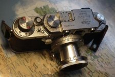
I was wrong stating earlier that screws were gone with introduction of Red Dial. I just came accross Red Dial 628785 which still has four screws, My other red dial SN in a range of 720xxx does not have screws, neither shell has holes. As usual, in transition time you could possibly find shells with holes but top cover without screws
I was wrong stating earlier that screws were gone with introduction of Red Dial. I just came accross Red Dial 628785 which still has four screws, My other red dial SN in a range of 720xxx does not have screws, neither shell has holes. As usual, in transition time you could possibly find shells with holes but top cover without screws
Attachments
traveler_101
American abroad
Not sure if statistics matter in your research, but I'll throw my report in; it confirms what you already have read: 1951 IIIf BD has screws.
Mr_Flibble
In Tabulas Argenteas Refero
This is definitely true. Also with the upgrades Leica offered you might run into a different type of camera than the serial number would suggest.As usual, in transition time you could possibly find shells with holes but top cover without screws
Different style top covers for a particular model is something I've run across a few times. Certainly with III and IIIa cameras.
Well, it's not like I'm writing a book or anything. But it's an interesting detail to know about the evolution of the design.Not sure if statistics matter in your research, but I'll throw my report in; it confirms what you already have read: 1951 IIIf BD has screws.
Mr_Flibble
In Tabulas Argenteas Refero
I've run a test roll of film through the IIf RD, the camera is fine but needs a small tweak to the rangefinder. And 1/30th instead of 1/25th is not a big deal.
But the 50mm f/3.5 Elmar that came with it needs help. There is too much play in the lens tube and/or focusing mount. One of the bayonet lugs of the tube has broken off, probably when the camera hit the pavement.
For a solution I'm thinking of turning this into a non-collapsible Elmar by glueing the lens tube in place in the focusing mount . 😉
dotur
od karnevala
My IIIf RD 621286 has four screws.
Jerzyw
Member
There is too much play in the lens tube and/or focusing mount. One of the bayonet lugs of the tube has broken off,
broken lug might not be a problem, there are still other two. 😉To eliminate play between the barrel and focusing mount I would try with replacing the velvet in focusing mount before converting into fix Elmar (althugh it would be then very unique and maybe reaching in something like 50 years a collector value as a "prototype" 🙂
Mr_Flibble
In Tabulas Argenteas Refero
The missing lug causes some sideway movement of the front of the lens. And I think the focus mount threads are damaged as well as there's some some forward/backward play on the mount.
I'll see about replacing the velveteen first, before doing anything drastic 😉
Ah well, another chance to take an Elmar apart. An opportunity to clean the lens surfaces and smooth out the aperture movement.
I'll see about replacing the velveteen first, before doing anything drastic 😉
Ah well, another chance to take an Elmar apart. An opportunity to clean the lens surfaces and smooth out the aperture movement.
Dralowid
Michael
If you are going to pull the Elmar apart can you do a step by step for those of us who find it a bit of a wrangle?
Michael
Michael
Mr_Flibble
In Tabulas Argenteas Refero
Check. I'll snap some pictures when I get round to it. 😉
Dralowid
Michael
Thanks, that would be great!
Jerzyw
Member
the lugs are 0.7mm thick on the right side and 0.95 on the left (at least on the Elmar on which I am working now). Although hard to believe that the lug could be broken on camera hit (other damages would be much more visible), who knows. Anyhow, due to increasing thickness you should be able to fix the lense if turn enough when locking. You should have no play forward-back. You might possibly have some play up-down due to missing lug, but this should be compensated with new, maybe slightly thicket velvet.
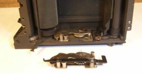
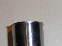
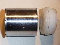
Inserting the barrel into focusing mount is always tricky. Therefore i made a tool for myself, see foto. On one side it goes into barrel, the other side is smaller in diameter and this is where the focusing mount is pushed onto.
Inserting the barrel into focusing mount is always tricky. Therefore i made a tool for myself, see foto. On one side it goes into barrel, the other side is smaller in diameter and this is where the focusing mount is pushed onto.
Attachments
Jerzyw
Member
..one thing more....taking Elmar apart requires that the inner lens barrel is unscrewed and removed. Unscrewing the retaining ring on red scale Elmars is problematic, due to the black paint used. it is sticky and it may fully block the ring after few turns, it goes between the windings. Therefore I try to remove as much of this black paint as possible before I start unscrewing. Of course, after assembling you need to apply new anti glare paint.
Mr_Flibble
In Tabulas Argenteas Refero
Thanks for the tips.
Concerning paint in the threads, That explains why someone before me already stripped most of the paint and damaged the screw driver slots in the retaining rings. -_-
Concerning paint in the threads, That explains why someone before me already stripped most of the paint and damaged the screw driver slots in the retaining rings. -_-
Similar threads
- Replies
- 2
- Views
- 692
- Article
- Replies
- 7
- Views
- 2K
- Replies
- 0
- Views
- 500
- Replies
- 25
- Views
- 2K