Soldering a coil back on a pcb?

sheepdog

Available darkness.
Local time
1:25 AM
Joined
Jul 24, 2005
Messages
96
Hi!

I have had the worst of luck with my Scan Dual IV this autumn, managing to break it again just after I fixed it.
I postponed fastening the plastic cover because my ADD tendencies make me unable to finish any project properly before starting a new one, and after scanning the roll that I'd waited two weeks to see, I decided to move to the livingroom to continue the work. Did I even consider not lifting by the cover? Nope.

It flew much like a giraffe would, and contracted exactly two symptoms.
- the light does not come on when I push the power switch with the power chord connected.
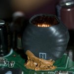
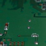
- a coil located near the power input on the pcb is hanging by the gummy insulation film.

Would I be able to fix this? Would it be easier to do so by attaching wires from the contact points on the coil to those on the pcb? Any suggestions on reassuring information on how to proceed?
 
Last edited:
Unless you are absolutely certain which connection the loose wire should go to, you are likely to only make things worse. I'm afraid you might have to bite the bullet and buy a new scanner...
 
Long delay, there, but I've been busy beyond belief.

I'll let the pictures complete the story, but it seems there are two points of contact, and that only one of these is broken.
One picture is of the coil itself, the brown goo on the bottom is cracked where one pin has broken. The other is of the backside of the PCB and shows the two solder tabs.

Is this an off-the-shelf part I could get via a part number in a repair manual? Would it otherwise be possible to re-use the broken coil by soldering wires between it and the PCB?
 

Attachments

  • PICT0309.jpg
    PICT0309.jpg
    39.6 KB · Views: 0
  • PICT0316.jpg
    PICT0316.jpg
    30.4 KB · Views: 0
If you've never soldered electronics before, I would suggest not attempting to fix it. If you overheat the PCB, it will cause the copper to separate from the board, then it will be much harder to fix.

However if you know what you're doing, you could probably just unloop a turn from the coil so you have some wire to work with. It probably wouldn't change the impedance enough to make a difference. Just be careful when you're removing the rubber cover of the coil, that you don't scrape the wires, which will remove the insulation.

One more thing, was there a possibility that the PCB got a static spark to it, at any time? That might also have damaged it.
 
Last edited:
You could measure the impedance of the part using a multimeter and then could just order a new coil from any large online electronic components dealer (digikey comes to mind).

If you don't move your scanner much, I would suggest trying to find some low-temp solder material. You can then solder the coil in place with a simple match or lighter.
 
1) check visually, if the coil is actually disconnected/broken off, and that there is no damage to the pcb.
2) take it off the board, by using a small solder iron from below the board. Don't overheat the board.
3) clean the solder points with a desoldering pump; you should clean it enough to see the original holes.
4) either by measuring the coils inductance, or by getting access to the circuit diagram, get the coils dimension, and buy an off-the-shelf part
5) solder the new part back in.

If this coil is close to the board's power input (in series to the main AC line), it might be just for power cleaning/spike removal. You possibly could just short it with a wire and the scanner might work.

All this at your own risk ....
 
Last edited:
Thanks guys, that was almost scary quick! :)

The coil is almost the first component after the power input, so my flatmate also suggested shorting it. Would a spike on connection destroy other components if not for the coil? I think this would be my last choice, but it's nice to know there is a plan B.

I suppose I'll try unwinding one round of wire first, and order a replacement if I manage to screw up. Plan C would be a V700 to be able to use my TLR and Folder MF-negs for something useful..
 
A spike can do all kind of things, depending on how large it is and on what's behind.

But remember that the scanner is sold all over the world, the Norwegian power net is likely much cleaner, than, say, the Californian (where I live, not kidding).

When you unwind the coil, you will have to remove isolation (orange color) from the end. You can just scrape it off with a knife.

Good luck !

Roland.
 
The coil is almost the first component after the power input, so my flatmate also suggested shorting it. Would a spike on connection destroy other components if not for the coil?

No, shorting it might really screw it up, depending on its precise purpose in the circuit.
 
Yup, shorting it seems like something of a desperate measure at this time. I'll just need to borrow my flatmate's soldering iron when he's back on monday and see what I can do. to fix it properly.
 
Short it - what have you got to lose? Obviously it was insufficient to kill whatever surge came down the mains and replacing with the same value would be an excercise in futility. The original coil was inadequate so why replace it with another of the same value? If you do want to replace it, talk to someone who knows about power supplies - a Ham radio operator?
Murray VK4AOK
 
I think the coil is damaged because he dropped it, and it partially broke off, not because there was a surge.

Personally, I would avoid shorting it unless you are desperate - at the moment, it sounds like a simple repair, just soldering a part in, but if you short it and damage other parts it could get complicated and expensive very quickly.
 
Shorting it would be a bad idea I think. And coils rarely break. To me it looks like the pcb is damaged. A coil like that is to heavy to be held in place by just soldering it to the pcb. Appearantly the glue also was insufficient in this case. Propaply you will have to scrape off some of the green laquer on the trace to expose the copper and then try to solder the coil to it.

/Ola


+1

I would be pretty concerned that the underlying trace was lifted/ripped when the coil lead pulled out.

I had a portable shortwave radio suffer a similar demise. PCB's simply don't suffer physical trauma well.
 
Try and get the coil off as cleanly as you can. As I said ask about and find a ham radio man. He will have a small soldering iron. These things work at less than 10W. The coil you describe is usually the surge suppressor and is followed by a voltage clipper before it goes into the rectifier. It may be that there is a switchmode power supply following, in which case the coil can be bypassed temporarily to try out the machine. If the coil is part of the switchmode power supply - nothing will happen. Put more bluntly- you're up the creek anyway. A repairman would be hard to find and the cost would doubtless appoach the cost of a replecament.:mad:
You see these coils in light dimmers. They are to cut down the electrical noise generated by triacs getting back out thru the mains to places you don't want it - eg radios/TVs etc.

Sorry
Murray
 
You will need
30-40w soldering iron
Resin cored solder for electronics
Solder sucker
Silicon
Steady hand
Light


Unsolder the other connection and take the coil off the board.
Slit and remove the heatshrink. Unwind 1 turn of the coil on the broken end. Cut the wire to length with about 1/4" excess.
Scrape the enamel insulation off the wire and tin the end with some solder. Apply the iron soldering iron and solder at the same time.
Clean out the holes in the pcb using a solder sucker. Fit the coil back onto the board and solder into place. Run a bead of silicon around the bottom of the coil to hold the coil steady.


See how you go.
 
excuse me, but supposing that it's inadequate for its purpose and it's useless means all the minolta electronic engineers are stupid who spend extra money on including something without a function isn't it?

I'm sure u can solder it back if you feel like trying.
 
Back
Top Bottom