wolves3012
Veteran
Spyderman,
I can see a few problems with your circuit, sorry to pour cold water on it...
1) I can see what you were thinking in the circuit, but with no hysteresis the minutest changes would make the LEDs go on & off like mad at the "null" point. A has been suggested elsewhere, an op-amp , with feedback, would be a better choice.
2) Comparators are prone to latch-up . The resistance of a CDS cell can fall to a couple of hundred ohms in bright light, enough to take the inputs close to +ve supply and cause latch-up. Lack of supply decoupling in your circuit (presumably you'd want small batteries) would make that even more likely. You need to limit the input voltage swing by inserting suitable resistors in both sides of the input chains.
3) There is a huge variation in intensity to be catered for, which may mean that your "meter" is not useful in some situations.
4) A CDS cell may simply not be sensitive enough to be useful when using reflected light off a white patch on the curtains - I may be wrong on that since I've never tried it but it could be a deciding factor.
5) There will be sensitivity to voltage change as the batteries age. A bridge circuit to find a null point would be immune to such changes to a large degree. A dual op-amp would allow one amp to be used for the bridge and the other as an inverter to give the over/under indications. It would be easy enough to get a mixture of LED colours that way too. Be generous with supply voltage too, something like a 12V cigarette-lighter/car remote-locking battery would be better than a couple of cells (PX23 springs to mind but I may have that wrong). Comparators and op-amps generally have poor performance on 3V or so.
I'm not claiming to be an electronics expert, but it's been a hobby for many years. I'd be happy for you to prove me wrong on any of the above! Oh, and if you go ahead - good luck!
rxmd
May contain traces of nut
Hi Ondrej,
here's a bump and a few suggestions. Disclaimer: I'm not much of an electronics guy apart from a hobbyist's interest, so my suggestions might be complete rubbish. Anyway:
- how about using an SBC phototransistor/photodiode instead of a CdS variable resistor? That way you get a much better sensitivity range. All camera vendors started to use SBC in the 1980s, there is really no reason not to follow their example. Especially when you want to read reflected light off the curtain!
- there should be a switch somewhere to switch the meter on and off.
- there should be some way of compensating for voltage drop. Either put Vcc through a small regulator circuit or use a dual opamp or both.
- there are dual-colour LEDs that are just two LEDs in one case with separate inputs, these would be easy to adapt for this purpose. Red for underexposure, green for overexposure. If you drive both at once, you get yellow.
- even though his microcontroller approach was rather complicated, you might still be interested in Huw Finney's project. He actually made two different versions. The first one used a light-to-frequency converter and read out the frequency using a microcontroller, that's the one you refer to. He later dropped that due to poor battery life. The second one (described here) uses a phototransistor and an opamp/comparator circuit. He then hooks this up to the microcontroller. I guess it would be possible to do without a microcontroller as well. He uses the microcontroller (a) because he apparently likes microcontrollers, (b) because you can do some things more easily in software, such as linearity adjustments or possibly different sensitivity ranges (i.e. ISO selector). I got interested in fitting my Kiev with an TTL meter and asked him for his schematics files, which he sent me; I guess I could forward them to you if you're interested. I also like his idea of putting a thin PCB under the bottom; that way one approach would work for most FSU cameras.
I'm very much interested in your project, partly because it scratches an itch I've had for some time. If you decide to continue in this direction please keep us updated. After September when I'm back in Europe I might get in touch with you about it.
You're next on my list for the FED from Pass the RF III. Any FSU photo gear you might want in the same package? I can look around and see if I can find something.
Philipp
Spyderman
Well-known
Thanks for comments guys...
I'm also not very good at electronics - that's why I posted it here - to getsome feedback and comments (bad AND good).
I chose CdS cell, because they are cheaper and easier to find.how about using an SBC phototransistor/photodiode instead of a CdS variable resistor?
That's why I thought of it as a substitute for Sunny16. Not a real meter for extremely low light...There is a huge variation in intensity to be catered for, which may mean that your "meter" is not useful in some situations.
I thought comparator comparing voltave drop on CdS and on a fixed calibrating resistor is supposed to be supply voltage independent... right?there should be some way of compensating for voltage drop. Either put Vcc through a small regulator circuit or use a dual opamp or both.
Sorry - I don't understand this...Comparators are prone to latch-up
Please try to draw a scheme.. I just don't get itYou need to limit the input voltage swing by inserting suitable resistors in both sides of the input chains.
They are available in many ranges. I thought about using one with resistance up to 0.5Mohm in complete darkness. But the truth is that I have no idea how much light will actually reflect off the curtain and how much it will change the resistance of the cell... I'll have to find out empirically...A CDS cell may simply not be sensitive enough to be useful when using reflected light off a white patch on the curtains - I may be wrong on that since I've never tried it but it could be a deciding factor.
wolves3012
Veteran
Spyderman said:I thought comparator comparing voltave drop on CdS and on a fixed calibrating resistor is supposed to be supply voltage independent... right?
No - untrue - hence the superiority of an op-amp and bridge circuit. It may be near enough for the purposes you desire, however. In any case a potential divider consisting simply of a chain of resistors (effectively what you have) will always be voltage sensitive. The comparator will also have properties that vary a little. As I said, these factors may not be enough to worry over in reality, but worth considering as possible errors.
Sorry - I don't understand this...
Latch-up is a condition where the inputs are too close (voltage-wise) to the supply rails. In these conditions the output is unpredictable and "latches" to one rail, refusing to change until the circuit is powered off or the inputs change drastically.
Please try to draw a scheme.. I just don't get it
I'll have a go, be patient though!
They are available in many ranges. I thought about using one with resistance up to 0.5Mohm in complete darkness. But the truth is that I have no idea how much light will actually reflect off the curtain and how much it will change the resistance of the cell... I'll have to find out empirically...
I have no idea either, hence just pointing out that they *might* not be suitable.
Whoops - that quote wasn't quite as expected - hope it's clear though
Last edited:
Spyderman
Well-known
Bump... 
Just wanted to let you know I just picked up the ordered parts: comparator (LM339) and some CdS photoresistors (VT93N2) ... and I hope I'll be able to move this project further...
Do you have any new ideas guys? Any schemes for me?
Just wanted to let you know I just picked up the ordered parts: comparator (LM339) and some CdS photoresistors (VT93N2) ... and I hope I'll be able to move this project further...
Do you have any new ideas guys? Any schemes for me?
40oz
...
IMHO, calibrating it to just one ISO is preferable. In other words, if the "meter" says I'm golden at 1/15 @ ISO400, doing the math for whatever film I'm actually shooting is cake. It's how I use my Canonet all the time. Considering which ISO to calibrate for depends on the sensitivity of your sensor. I'm not sure the world needs yet another meter that only works on sunny days, however
But if you get it actually working in any configuration under any conditions at all, I'd think most of the work would be done. Then you can play with resistors and sensitivity until it's perfect and minimal 
Spyderman
Well-known
After an advice from my friend today I bought me a "solderless breadboard".
I already assembled the circuit but it's not working yet...
It seems to work, but with supply voltage of 6V there is only 0.5V on one of the outputs and 0V on the other. Any help would be greatly appreciated...
I already assembled the circuit but it's not working yet...
Spyderman
Well-known
Oh my God! it's working!
the problem was the connection of LEDs. They should be between supply voltage and comparator output, not between comparator output and ground! After seeing this page ( http://home.cogeco.ca/~rpaisley4/Comparators.html ) I reversed the LEDs and it's working!
Spyderman
Well-known
thafred
silver addict
Great Ondrej!!
glad to hear your idea is taking form!
I´d be very interested to know how you will couple it to the shutter, I don´t have any idea how this can be done, oh and in what camera are you going to put it again?
congratulations anyways! sweet project
glad to hear your idea is taking form!
I´d be very interested to know how you will couple it to the shutter, I don´t have any idea how this can be done, oh and in what camera are you going to put it again?
congratulations anyways! sweet project
Spyderman
Well-known
Any camera
but I'm going to try it on a FED-3, then all the rest... 
Spyderman
Well-known
I've got some good news.
The circuit itself is still outside assembled only on a "solderless board", but I've tried to place the CdS light sensor inside of a FED-2 body, with a piece of paper placed on the shutter curtain (to simulate white paint on shutter curtain) and lens mounted where it should be, and . . . it's working!
By opening and closing the diaphragm of the lens I am able to find the point where the LEDs switch. There is no point where both are off, but there is a very limited range where both LEDs are "slightly on". No hysteresis problems as someone suggested earlier. Setting the switching point is just a question of calibrating reference resistor.
Now I'm looking for help from someone who knows how to use circuit board designing software (like Eagle or something else). I'd need to design a circuit board with SMD components the size of self-timer in FEDs and Zorkis - 38 x 16 mm.
If you can help, please send me a PM.
Last edited:
Spyderman
Well-known
This is a post to sum up what has been said in earlier posts.
I suppose the meter would be calibrated for (shutter speed = film speed) thus it would work with all aperture values of the lens mounted. It would not be good for very low light, but it would help in those situations when sunny16 is difficult to use (late afternoon, in shade...).
For example I can use sunny16 with good light from f16 to f5.6. At dusk or in shade I'm lost without a meter. But this meter can measure light from f16 to f2 or even f1.5 if you have Jupiter-3 mounted!
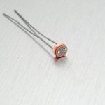
Experimentally I found that with the cell I use VT93N2, with the amount of light for correct exposure (with sunny16 rule) hitting the shutter curtain, the resistance of the CdS cell is about 80-100 kOhm.
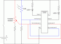
And this is the correct circuit:
Note:
It would be possible to use more calibrating reference resistors for use of shutter speeds other than (shutter speed = film speed) and a switch somewhere on the camera body to select which resistor is used.
For example 2 additional calibrating resistors: 1 for shutter speed 4-times slower and one for 16-times slower. So with ASA400 film, you could use the built-in light meter with 1/500, 1/125 (4-times slower) and 1/30 (16-times slower). This is already the full range of shutter speeds of FED-2 !
The problem is there would have to be enough space for the extra variable resistors on the circuit board and the placement of the switch. If you could mount this into a Kiev-4's meter housing, it might be possible to incorporate the additional VR and the switch, thus widening the light conditions in which this meter would be usable.
- I'd like to make a built-in TTL light meter for Zorki and FED and possibly any other camera with enough space to fit it inside.
- use CdS light-dependent-resistor because they are cheap, small and easily available (particularly I use VT93N2 )
- place the sensor in similar way like Voigtlander Bessa series - facing the shutter curtain
- the shutter curtain would need to be painted white (or grey, but we need as much light reflected as possible)
- the circuit itself should be small enough to fit inside the body of FED or Zorki instead of the self-timer mechanism (which is 38 x 16 mm).
- the circuit as I designed it is completely voltage-independent. As long as there is enough juice to turn on the LEDs the meter will give correct reading.
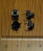
- the self-timer release button would turn on the meter
- meter readout would be by two LEDs of different colour in/near viewfinder (could easily be placed next to viewfinder eyepiece similar to "flash ready" indicators on P&S cameras to be visible from outside)
- battery could be placed between lens and shutter (I suggest 3V lithium button cell CR1632 with 16mm diameter)
I suppose the meter would be calibrated for (shutter speed = film speed) thus it would work with all aperture values of the lens mounted. It would not be good for very low light, but it would help in those situations when sunny16 is difficult to use (late afternoon, in shade...).
For example I can use sunny16 with good light from f16 to f5.6. At dusk or in shade I'm lost without a meter. But this meter can measure light from f16 to f2 or even f1.5 if you have Jupiter-3 mounted!
Experimentally I found that with the cell I use VT93N2, with the amount of light for correct exposure (with sunny16 rule) hitting the shutter curtain, the resistance of the CdS cell is about 80-100 kOhm.
And this is the correct circuit:
Note:
It would be possible to use more calibrating reference resistors for use of shutter speeds other than (shutter speed = film speed) and a switch somewhere on the camera body to select which resistor is used.
For example 2 additional calibrating resistors: 1 for shutter speed 4-times slower and one for 16-times slower. So with ASA400 film, you could use the built-in light meter with 1/500, 1/125 (4-times slower) and 1/30 (16-times slower). This is already the full range of shutter speeds of FED-2 !
The problem is there would have to be enough space for the extra variable resistors on the circuit board and the placement of the switch. If you could mount this into a Kiev-4's meter housing, it might be possible to incorporate the additional VR and the switch, thus widening the light conditions in which this meter would be usable.
Last edited:
Spyderman
Well-known
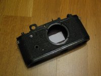
Here's my "FED-2 test body":
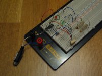
The circuit assembled on a solderless board:
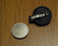
and the suggested battery holder and a CR2032 battery. This is slightly too large to fit inside so a CR1632 with apropriate holder should fit.
I'm still looking for help with designing the circuit board !
The circuit assembled on a solderless board:
and the suggested battery holder and a CR2032 battery. This is slightly too large to fit inside so a CR1632 with apropriate holder should fit.
I'm still looking for help with designing the circuit board !
Attachments
Spyderman
Well-known
zuikologist
.........................
Very cool project - I look forward to the results. Do you have a mean of calibrating/recalibrating the meter if needed?
acheyj
Well-known
Hey Syderman.
First of all had a whole bunch of reasons why it wont work, however reading all the post just maybe.
Your idea of emulating the sunny 16 will vastly simplify things. Before I gave up photography late 60's I built a densitometer and later an enlarging exposure meter (I went insane on the Zone system !). Things to watch out for.
1. Stable voltage (will need a vr)
2. Spectral sensitivity the cds I had to work with were red sensitive and lacking blue.
3. Temp sensitive .
Size today is not so bad as surface mount components are really really small, get somebody to do the circuit board and stuff after you have proven up the design on a breadboard. You certainly would find it easier to use a micro-processer for a full blown TTL but thats not your intention. Find a local ham (amatuer radio operator) who dabbles in tracking satellites, we tend to be also slightly demented !. He/She will be a big help and wont cost you (I built my complete computer controlled tracking station from scratch).
I wish you luck and will watch progress with intense interest. You realise of course it will be much cheaper to use a ps digital thing and the prints will be better than 35mm, however thats a side issue and not relevant.
ron (gee I wish I was young again) VK5AKJ (acheyJ)
Murray Kelly
Well-known
Ondrej, you don't tell us how deep the board can be. It sounds like plenty of room and remember there can be two sides to the board, given enough depth.
I will run this past my son who designs this stuff at his work. He made me a very nice digital speedometer for my car.
I will question him about linearity and voltage drop issues.
Using surface mount components it should be a shoe-in.
The switches are a common component - I know them well since I had to replace a bunch in one of my tranceivers.
Good luck with the project.
Murray VK4AOK
Spyderman
Well-known
Well, no news since my last posting, but for Murray: the available height is about 10mm, maybe 8.
My friend was helping me with the board, but he has a lot of work now and no time for my crazy projects.
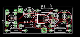
I'm attaching my friend's design of the board (of course the LEDs won't be on the board but there will be wires attached and LEDs will be inside or near the viewfinder). This is just the first version, so take it as such.
Attachments
lex
Established
looks promising!
take a look at the olympus OM2 shutter curtain (the pattern the meter gets reflected light from). the cds metering on this guy is renowned for its... well, lets just say it is a good meter!
Share:
-
This site uses cookies to help personalise content, tailor your experience and to keep you logged in if you register.
By continuing to use this site, you are consenting to our use of cookies.