literiter
Well-known
optikhit,
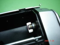
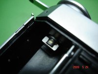
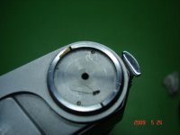
I have this camera with the Prontor shutter. To remove the front element of my lens, I merely gripped it with my hand and turned counter clockwise to remove. It was quite stiff, but off it came. (This was only the lens of course. The shutter remained on the camera.)
Vincent
I have this camera with the Prontor shutter. To remove the front element of my lens, I merely gripped it with my hand and turned counter clockwise to remove. It was quite stiff, but off it came. (This was only the lens of course. The shutter remained on the camera.)
Vincent
Last edited: