Hi,
My experience is that it's usually a mechanical connection, not the electronics. So a bit of use and the corrosion or dirt is dealt with by friction. But that's not as good as doing it properly.
Guessing now, the cell swings down, suggesting a mechanical and electrical link. And those little batteries and so on are not the most powerful so are easily upset by dirt etc.
Regards, David
I agree that most problems with old cameras seem to be mechanical or at least depending on oxide on electrical parts from lack of use or manipulations.
My CL also had a problem with a meter showing wrong measurements. I tried to adjust the ISO setting, it helped but for Tri-X the camera setting was about 64 ISO! The needle swung and was difficult to get started, I had to change the shutter speed up and down.
Yesterday I finally adjusted the exposure meter. While I was at it I also cleaned the finder.
There is an instruction how to trim the CL meter:
http://photo.net/leica-rangefinders-forum/00C1kg
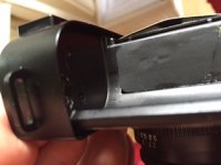
I tried instruction this first, but I could not get it right. Everything become worse. The instruction is correct, but perhaps I had too little patience. The trim resistors can be found in the film box side, see picture. I glued back the black cover i my CL. There is four trim resistors for ordinary small 2 mm screw drivers in tiny small holes. The trim resistor to the bottom of the camera adjusts the battery check. I guess the top trim resistor is in series with the galvanometer (the meter needle). The two in the middle must be for for linearity.
I tried and tried, but did not get this right. The needle become stuck at the top in the finder. I started to think that the galvanometer was damaged. I then decided to take the top of the Leica CL to see what was wrong.
The top is easy to take off. You take away the screw under the winding lever, take away the winding lever by screwing the top part off and screw off the cover of the shutter release. To do this I covered my plier with electric tape to avoid marks, but I still got some marks. I should have manufactured some flexiclamps.
Finally there are two screws holding the top strap lug. They are located inside the camera in the film box part. One of these was almost stuck for me. When you get these loose, you can lift the top off. Be careful so that you do not loose the distance for the top screw under lever. It is a small, about 3 mm cylinder, standing on the camera. The lug is also loose. I did not take any pictures, but these links are good:
https://garbugli.wordpress.com/tag/leica-cl/
http://justinlow.com/articles/repair-leica-cl
I took the battery away and measured the resistance of the circuit with activated meter by moving the winding lever out. Otherwise the circuit is off. The resistance was about 4 kohm, the resistance of only the galvanometer (needle) was 3,2 kohm. So the circuit was not broken, it must be something else which is wrong. It is interesting how Leica has solved the problem of adjusting the meter if the ISO or the shutter time is changed. The complete galvanometer set-up is then rotated with a mechanical linkage when you change shutter time or ISO speed! Typical Leica, I would have solved this electrically!
As the electrical circuit seems OK, I sprayed some very few drops of 5-56 on the galvanometer and the contacts at the windeing lever. This solvent, 5-56, is a rust and lubricating solvent we have here in Sweden which also takes oxides away.
I also cleaned the glasses in the finder. Most of the dirt was on the inside of the removed top. I did not touch the range finder glasses. They seemed very delicate, but was already clean.
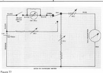
The electric circuit of the meter puzzled me. I found this circuit for a M5 meter on the net, see figure. It is taken from:
http://www.l-camera-forum.com/leica-wiki.de/images/a/aa/TheCamera_Craftsman_Leica_M5.pdf
As the CL and M5 is almost of the same age, I guess many things are similar. As the old mercury cells give almost constant current the measurement circuit is not a bridge, it is a current measurement circuit. The galvanometer with the needle measures current. The cds-cell is a variable resistor. When it is dark the resistance is high, when it is light the resistance decreases, but not in a linear way.
I guess the top trim resistor in CL is VR2 in the figure. The bottom trim resistor must be VR1. The two in the middle must be something similar to VR3 in the figure, to adjust the linearity of the circuit. I guess they are parallel. Their purpose is to give steady load in circuit, to reduce the variation of the current depending on the cds-resistor. The values of the also influences how much current which flow through the galvanometer. With high values, more current and a larger deflection in the meter.
The galvanometer is therefore adjusted for a particular current. The needle is then in the correct position when the light is correct. But when we adjust the time or the ISO we rotate the meter. The meter must therefore be corrected for different shutter times (and ISO settings).
I measured the resistance of the circuit when I rotated one trim resistance. The resistance changes only during one complete rotation, it is of no use to rotate more. It only rotates and repeates itself.
I started again to try to adjust the meter. I measured with a reference meter, my Sekonic to get a proper value. I used this aperture and worked with the shutter speed. I now tried the two middle trim potentiometers first. I slowly changed one of them and observed the finder. I tried to move the trimmer (with very small turning angles) to get correct reading, so that the shutter speed would be correct. When I could get no nearer I changed to the other middle trim potentiometer and continued. At last I tried the very sensitive top trim potentiometer. This trim potentiometer is sensitive even for presence of the screw driver. Be very careful! Finally the reading became correct!
I measured with the Sekonic a new lighter part of my home (better lamps!) and made the adjustment process once again. Now it was more easy to find the correct values, not many adjustments were necessary. I the went back and checked the original light condition. It was OK!
Finally I adjusted the bottom potentiometer for battery check, so that the needle swings into the notch when I press the battery check button and the shutter speed is chosen so that a marker is visible at the top in the finder.
Finally everything was OK. A very clean finder and a working meter at all ISO. But I got some scratches on the winding lever during work on my CL. I will try some black nail colour. I must also make some flexiclamps. This was fun
🙂