Hexar RF - RF window - top plate removal ?

gliderbee

Well-known
Local time
10:24 AM
Joined
Mar 2, 2008
Messages
750
I just received my Hexar RF with the 50/2 lens.

Everything seems to be working fine (motor, shutter, rangefinder, etc...), but I didn't take any pictures yet with it.

The left side (when looking at the front of the camera) of the RF illumination window (the white "striped" window) is a bit offset to the back (see picture below).

I don't think that's how it is supposed to be, is it ? I guess I can just push it back if I can remove the top cap ? Is there anywhere a "repair manual" or something that explains how to remove the cap ?

Thanks for all help,

Stefan.

Here's a picture of the "problem":

sized_hexar.JPG
 
From memory.

You have to undo the film speed setting dial by finding something suitable to insert into the two small pin holes and turning it (I used some needle nosed pliers).

Then undo the tiny screws securing the top plate. I recall there is a little hidden screw just below the front of the viewfinder which is hidden underneath the rubber grip next to the frameline lever.

It should come off easily after that.

Good luck!

Bob.
 
If memory serves me well, all of the front glass is glued/cemented in. If it is coming out/pushed back, it will need to be re-cemented.
 
Ok, done ! Thanks everyone for your advice.

I glued it back in with Microscale "Micro Krystal Klear", just the right stuff for that kind of job.

Stefan.

If memory serves me well, all of the front glass is glued/cemented in. If it is coming out/pushed back, it will need to be re-cemented.
 
I have exactly this problem with one of my Hexar RF bodies too - mine isn't quite as bad as in the photo above, but if you put pressure on the left hand side of the illumination window then it pushes into the body.

How tricky is it to remove the top plate and fix it? The pictures in the original thread about removing the top plate for rangefinder alignment no longer seem to work, so it is hard to tell.

Never Satisfied also mentioned above that the plastic illumination window was screwed into the metal as well as being glued. Is this definitely the case for all Hexar RFs?

Given that mine isn't too bad at the moment, I might just leave it for now if there are some screws still holding it in place. On the other hand, if it is just glue on the other side, I want to fix it ASAP in case the glue on the other side comes unstuck too.
 
Last edited:
I had this problem on my Hexar RF too. It was caused by myself lifting the camera from the bag and putting a finger on that frosted window, which came lose at one end.

I fixed it by using a proper screw driver and armed with the description of taking off the top it was easy. One screw is hidden behind the rubber cover. I put a tooth pick into each of the small holes of the speed wheel. Then I used a plier to grab the wooden tooth picks a bit up and unscrewed it.

Microscale Krystal Clear is a weak but friendly glue. If I remember it right I used 2-part epoxy and was very careful only to get it where it should be. Then I put it into gentle press over night.
 
Yeah I went ahead and opened it up last week to fix the problem. I wanted to do it before I went away, because if it got worse while I was away from home it would be difficult to fix on the road.

I agree that provided you have the correct screwdrivers (which I already had from opening up my MacBook Pro), taking the Hexar RF top plate off to fix this is very straightforward.

For glue I used a kind of combined glue/sealant I bought from a modelling shop that was called Zap Goo if I remember correctly. This seemed to work perfectly for the job - it is clear so it doesn't matter too much if you get a little on the plastic. Also, because it can be used as a sealant too it stays flexible for quite a while and gives you plenty of time to make sure the piece is correctly positioned. So far it seems to be very solid, but I will update if I have any problems in the future.
 
Follow this link, it will take you to an old RFF thread that describes the RF adjustment and top plate removal. ...
...
http://www.rangefinderforum.com/forums/showthread.php?t=1937

The old images of top plate removal in that thread are gone long time ago. As I had to work inside the top plate on my HRF, I will post new images for the venue.

My sequence suggestion for your work under the hood:
  1. remove the front screw under the leatherette
  2. remove the other three top plate screws
  3. remove the ISO dial pin hole screw
  4. do whatever is required
  5. start reassembling with the ISO dial pin hole screw
  6. screw in the four top plate screws

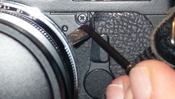
1) remove the front screw under the leatherette

As you can see, the 4th screw is - looking to the front of the camera - exactly a few mm below the left corner of the viewfinder window and left of the frame line lever. It is enough peeling gently a little bit of the leatherette to access this screw.

sml_U41720I1324819536.SEQ.0.jpg


All four screws are very small. And: They are not the exactly same lenght. The screw under the leatherette is the shorter one. Keep it in mind for reassembling.

2) remove the other three top plate screws

sml_U41720I1324820153.SEQ.0.jpg


3) remove the ISO dial pin hole screw

There are many suggestions in the web how to release the ISO dial screw. After trying different DIY ways to release this last 5th screw (scratching the black top finish :bang: ) I gave nearly up. But a week later I found a standard tool which fits exactly these holes and gives you a firm grip.

sml_U41720I1324820351.SEQ.0.jpg

(This tool is normally used to handle o-rings)

After disassembling the ISO dial, be careful not messing up the ISO contacts. Completely dismantled it can fall apart in four pieces, but it is not required you disassemble this dial if you aim only at the rangefinder in yards. Here you see from left to right:

sml_U41720I1324820940.SEQ.0.jpg

  • The ISO dial tray with the numbered ISO selector still in
  • The exposure compensation +/- dial
  • The ISO screw

If you have to do some work at the on/off switch, the shutter release or the time dial, the flash socket, the windows or the eyepiece: It's all here in the top plate.

sml_U41720I1324821151.SEQ.0.jpg


4) do whatever work is required

Most revision activities are related to the rangefinder light paths, which are now open in front of you.

sml_U41720I1324924863.SEQ.0.jpg


5) start reassembling with the ISO dial pin hole screw

When you start reassembling the top plate, mount the ISO dial mechanism first and screw in place the ISO screw. Before mounting the four small body screws check the correct mechanic stops of the ISO selector and the exposure compensation +/- dial. If both functions seems to click and stop properly, check it against the shutter speed information in the viewfinder, because it is possible reassembling a completely dismantled ISO dial mechanism with a wrong starting angle.

6) screw in the four top plate screws

After this final shutter speed test fasten the smaller screw in the front hole and then the other three screws in the remaining threaded holes.

Your are finished. :)

sml_U41720I1324924975.SEQ.0.jpg


Needfull things for top plate removal:
- Sharp micro screw driver to peel off the leatherette
- Phillips X screw driver #0 for the four top plate screws
- O-Ring pliers for the ISO dial 2-hole screw (pins have to be smaller than 1 mm diameter)
 
Last edited:
Back
Top Bottom