Olympus 35 SP Seiko FLA shutter CLA

Local time
8:21 AM
Joined
Feb 24, 2011
Messages
47
Introduction

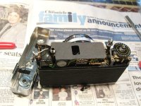
I have just finished overhauling my “new” Olympus 35 SP. I picked it up in Munich in January, from the “scrap” area of a big photo store, for 10 euro. No case, no strap, no lens cap, but the lens was clean, the overall condition reasonable and it fired on all speeds, although it was quite obvious it was slow. A low-to-medium amount of dust was gently covering it. An alkaline PX625A battery was inserted.
I didn’t pick it up just due to the price – it was a camera I was actually after and did not expect to get one so cheap. Of course, at the expense of my work, described below.
First of all, even if it may seem superfluous to the normal common sense, I do feel the need to point out that any attempt of performing these operations on your much beloved SPs are completely at your own risk! It’s a camera with a level of mechanical complexity way above average and it is extremely easy to lose, mis-assemble and destroy small but vital components. All the procedure was carried out according to my way of assessing things – there was no service manual implied. You’re free to say I was wrong on some points – pertinent and reasonable observations and corrections are welcomed. Bottom line, you have been officially warned!
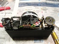
Second, even if I shouldn’t mention this, I can’t help not doing it: please make sure to use proper tools. Screwdrivers that don’t properly fit the screw heads are shortcut to a world of anger, irreversible destruction and frustration. Also, during reassembly, do not tighten the screws using the same force you use for the ones designed to fix heavy objects on your walls. Once you’ve ruined a 0.7 mm thread I don’t have any miraculous solutions for you. A simple digital camera with macro capabilities will do wonders: take photos of all steps and before removing anything. Don’t rely just on my photos. Of course I posted here less than a third of all of them. It would have been impractical to put them all. And please don’t ask me to post more photos – I’ve no idea when time will allow me to do that.
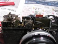
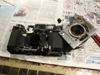
My sincere thanks to Brian Legge, whose tutorial here on rangefinderforum has helped me a lot. I hope mine will be of at least as much help for others. Since Brian has described the major disassembly of the lens assembly from the camera body, I see no point in repeating this in my own words – I couldn’t explain it better. I will however point some constructive differences between his camera and mine and give you an alternate way of separating the lens itself from its base.
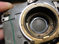
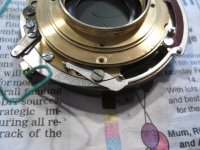
Brian, if you see this, you’ll also find the answer for your loose green wire :)

Let’s go on then!
 
First part: constructive differences

First part: constructive differences

First part: constructive differences

I’ve spotted three differences, one of which is major.
First, my rangefinder assembly was completely covered by a black carton mask, with a hole for the horizontal adjustment of the rangefinder. Brian’s rangefinder only seemed to have a small cover over the left part of the assembly (as seen from the rear of the camera) – image 1.
Second, the resistors on my camera are mounted on the rangefinder side of the circuit board. The circuit board is actually different in design, although the electrical connections are most likely the same – image 2. I will come back to the meter issue later.
Third, in my camera, there was no intermediate ring between the cocking one and the firing one – the one with just two tabs, which can be seen towards the end of Brian’s tutorial. My lens had obviously not been opened before (except for the front element), so that ring was not there from the very beginning. See image 8 (a little bit below) from my set versus Brian’s image. At some point they must have decided to either add or remove it – I’ve no idea whose camera is older between Brian’s and mine. Judging from the pressure plate marking, mine should be from March 1970, and the serial (unless the top has been changed) is 199664. Any help on precisely dating the camera would be deeply appreciated :)
That’s for the different parts, now let’s go for the real job.
 

Attachments

  • 01.jpg
    01.jpg
    186.9 KB · Views: 1
  • 02.jpg
    02.jpg
    181.6 KB · Views: 1
Second part: separating the lens assembly from the camera body

Second part: separating the lens assembly from the camera body

Second part: separating the lens assembly from the camera body

Brian has done a brilliant job in describing this. I just want to point out a technical captcha here. Take a look at my needle trap in image 3. You can see an obvious wear way above the eccentric adjustment screw. Why is that? Because some smart repairman decided to bypass the proper cleaning and lubrication of the shutter firing assembly seen in image 7 (a little bit below). It was not returning to its highest point after firing, therefore obstructing the meter needle. Instead of really solving the problem, this unknown hero busted the adjustment all the way to the opposite end to make space for the needle even with the firing assembly not fully back in its normal position.
Another point worth noting is that even if the manual says that AE goes from 1/15 to 1/250 in terms of shutter speeds, a quick view of the needle trap lets us now that the camera has 22 shutter speeds between 1/15 and 1/250. Not just 15, 30, 60, 125 and 250. The full image of this system will be completed when we open the shutter.
Watch out for the lower left corner of the rangefinder front window, which can be broken by carelessly trying to force the lens assembly off the camera body.
After removing the lens assembly I found the most likely reason why my camera was discarded: the power supply wire had come off because of corrosion – image 4. The alkaline battery found in the camera was actually new. So someone had tried it this way, saw it was not working and decided it was time for the camera to go. My luck. Once again, I’ll be back with the meter issue later on.
Finally take a soldering iron and unsolder the white and green wires from the back of the PC socket.
 

Attachments

  • 03.jpg
    03.jpg
    164.7 KB · Views: 4
  • 04.jpg
    04.jpg
    190 KB · Views: 4
Third part: separating the lens from its base

Third part: separating the lens from its base

Third part: separating the lens from its base – my way

Here Brian writes something like “remove the ring which is buried deepest”. Much easier said than done. First of all, my ring was covered by a degraded light seal. Most likely, its role was to prevent dust getting inside the camera while focusing close, when the “piston” represented by the lens sucks air inside the camera. For my peace of mind, I replaced it with a new one during reassembly.
Now back to that “deepest” ring. Trying to unscrew it directly brought no luck at all; moreover, I constantly feared I would damage the rear lens element.
After a little bit of frustration, I picked up an old effervescent vitamins plastic tube, cut off its top, cut a “V” along it to allow it to be squeezed and taped its inside with double sided adhesive tape – image 5. I put it around the rear element, squeezed it and, after a half turn initial slide over the lens… Bingo! The rear element started to unscrew absolutely naturally. Then, as you can see in image 6, the access to that “deepest” ring became quite easy and I could unscrew it really easily.
Then just take the lens off while carefully noticing the position of the shutter coking and firing rings. Image 8 shows the coking ring on the lens base. As mentioned before, no intermediate ring with two tabs going in the top and bottom notches of the focusing helicoid as in Brian’s case.
 

Attachments

  • 05.jpg
    05.jpg
    171.1 KB · Views: 3
  • 06.jpg
    06.jpg
    174.2 KB · Views: 3
  • 07.jpg
    07.jpg
    178.5 KB · Views: 3
Fourth part: lubricating the focusing helicoid

Fourth part: lubricating the focusing helicoid

Fourth part: lubricating the focusing helicoid

I’m not going to give a lot of detail here, since it’s not complicated at all. Remove the rangefinder pushing lever from the top rear part of the helicoid, remove the guiding metal piece from the lower rear part and simply unscrew it off. Watch out for the entering position – you can see the correct one in image 9, with the empty space of the helicoid at the 2 meters position of the focusing ring. Nevertheless, bear in mind the constructive differences mentioned above. Your camera may have a different helicoid entrance point – just remove it slowly and carefully observe the position where it escapes from the focusing ring.
Submerge the helicoid in lighter fluid to dissolve the old grease, then thoroughly clean every thread. I use a wooden toothpick for this. Remove the focusing ring from the base by unscrewing its rear retaining ring and the safety screw at the 7 o’clock position in the front. Clean and lubricate the contact surfaces between the focusing ring and the base plate using scarce amounts of grease. The shiny surface on the lens base, seen in image 10, is the one to be lubricated. Do not give into the temptation of generously lubricating the helicoid – it is really not at all recommendable. Just use as few grease as necessary to make things slide smoothly. I used white titanium grease for this part.
 
Fifth part: let’s get real – the Seiko FLA shutter (I)

Fifth part: let’s get real – the Seiko FLA shutter (I)

Fifth part: let’s get real – the Seiko FLA shutter

I’ll start this part by declaring loudly that I totally disagree with the method of “drowning” or “bathing” or whatever the full shutter assembly in lighter fluid. It’s like trying to wash your underwear by putting it inside your ski suit. Or like cleaning your room by sweeping the dirt under the carpet. You’ll only get the dirt randomly moved around. You’re free to do this, but the results are unlikely to get close to the desired ones.
Second, please understand that any type of shutter, but especially leaf shutters have their own maximal constructive speed. I know there are cameras out there with bold markings of 1/1000 for the speed of their leaf shutters. 1/500 is already kind of “overspeed” for a leaf shutter. It is perfectly obtainable, but it’s not sustainable on a long term. We are talking about pure mechanical shutters, driven exclusively by steel springs. It is simply against common sense to ask your 40 years old main spring to have the power to drive your shutter at the same speed it did 40 years and maybe 50.000 actuations ago. In this particular case, if your “1/500” gets close to 1/350, you’re right to give a party to celebrate this. You can trim the other speeds to match their designated values, but there’s nothing you can do to speed up the top speed of the shutter more than you can do it by a thorough cleaning. Except for finding a brand new, unused, main shutter spring…
Remove the three screws from the front, seen in image 11. When you close back the whole thing during reassembly don’t forget to fix them with an adhesive of your choice. Carefully take of the shutter speed and aperture setting rings. Inspect them on both sides, you may find some dust hidden in between. Remove the 5 silver screws that hold the black front shutter casing – image 12. Inspect this one also, you may find some dirt in here too.
So we’re on to the speed setting plate you can see in image 13. Here the shutter is set to its top speed, 1/500. Note the escapement mode selector – you’ll have to pull this from underneath the speed setting plate on reassembly. Take off the speed setting plate and admire the inner mechanics of the shutter, as seen in image 14.
Please note that the escapement has three adjustment screws. From left to right:
- lower speeds (1 – 4)
- AE speeds (15 – 250)
- manual higher speeds (8 – 250) (once again, the top speed of 1/500 is NOT adjustable)
As mentioned before, observe its lower lever, which is used by the AE system – it’s easy to see there are no steps here – as I mentioned earlier, the 22 steps in shutter speed are given by the needle trap above.
 

Attachments

  • 11.jpg
    11.jpg
    163.5 KB · Views: 3
  • 12.jpg
    12.jpg
    181 KB · Views: 3
  • 13.jpg
    13.jpg
    187.9 KB · Views: 3
Fifth part: let’s get real – the Seiko FLA shutter (II)

Fifth part: let’s get real – the Seiko FLA shutter (II)

Now is the right time for a second big warning: it’s at your own risk. Watch out carefully what you’re going to remove from now on. My advice is to put each sub-assembly in a separate labelled zipper plastic bag. And it’s not too late to stop if you’re out of adrenalin :D

Ready for the tough part?
Remove the inner cocking ring and its spring.
Now turn the whole thing over.
Remove the four screws seen in image 15 in order to remove the flashmatic system ring – it connects the aperture to the focusing ring. Please note that the heads of the upper and lower screws are smaller and those of the side ones are larger.
Remove the three screws that retain the AE shutter speed selector ring seen in image 16 – please note that the one around 6 o’clock has a different head.
Image 17 is for reference, with all aperture command levers in place. You’re going to remove (and of course clean) them in the next steps. Images 18 – 22 will help you during these steps.
Disconnect the mobile end of the aperture spring seen in image 23 (already disconnected).
Images 22 and 24 should give Brian Legge a good idea about where the green wire goes – to the flash sync contact on the shutter casing.
Remove the click stop system of the aperture seen in image 25. Please note that every one of its three screws is different, so pay the required attention on reassembly.
 

Attachments

  • 14.jpg
    14.jpg
    188.8 KB · Views: 4
  • 15.jpg
    15.jpg
    182.4 KB · Views: 3
  • 16.jpg
    16.jpg
    189.6 KB · Views: 3
Fifth part: let’s get real – the Seiko FLA shutter (III)

Fifth part: let’s get real – the Seiko FLA shutter (III)

Third big warning!
The three silver screws you see now are holding the shutter base plate to its casing. Namely they are closing the space for the shutter blades. Once you remove them, your shutter blades will be free! Please take a good look at the proper positioning of the blades. Also please note that the FIVE blade pins of the shutter are occupied by SIX blades, since the top position has a rear superimposing blade with the same position as the first front blade!

Take good note of the position of the various springs that lean one of their arms on the inner side of the shutter casing.
OK, now remove the three screws, tilt the shutter base plate lifting it from the escapement part (lower right in image 27) and gently remove it by eventually letting the self timer lever slide out through its slit. The shutter blades will all fall down and you’ll be let with the aperture and the shutter base plate with the mechanical parts as seen in image 28. Put the shutter blades safely aside.
Remove the screw circled in red in image 28. Do not forget about the underlying spring - don’t lose it and note its correct orientation. You now have access to the second screw fixing the escapement to the base plate – the first one is circled in green. Unscrew them and remove the escapement, as seen in image 29. Drown it in lighter fluid and let it soak. Similarly, remove the self timer mechanism (around 9 o’clock position, seen from the front – images 30 and 31) and give it also a proper lighter fluid bath.
You can also remove the self timer lever and the shutter firing levers, seen in image 32, in order to properly clean it and the underlying area. The axles of the firing levers may be lubricated with a scarce, scarce, scarce, (not a typo) amount of thin oil. (I can never stress enough how important dosage is when lubricating camera mechanical parts. If you can actually see the oil there after lubrication it’s already way too much.) You can give the same treatment to the coking cog wheel and to the B and flash sync levers seen in image 33. Carefully note the position of all springs before disassembly. Never forget to properly clean all contact surfaces between any moving elements!
Remove the screws holding the front lens element mount seen in image 35. You now have access to the shutter actuating ring, seen in image 36. It is of crucial importance that this ring is able to move as free as possible between the shutter base plate and the front lens element mount, so give all of these surfaces a proper cleaning – also see image 37. As in any leaf shutter, these parts are NOT to be lubricated, unless you use graphite. Once again, if you do, mind the quantity used! I left a faint TRACE of graphite on the surface of the actuating ring.
 

Attachments

  • 26.jpg
    26.jpg
    181.4 KB · Views: 3
  • 27.jpg
    27.jpg
    180.8 KB · Views: 4
  • 28.jpg
    28.jpg
    187.7 KB · Views: 5
Fifth part: let’s get real – the Seiko FLA shutter (IV)

Fifth part: let’s get real – the Seiko FLA shutter (IV)

Let’s now draw our attention to the self timer (images 30 - 31) and to the escapement.
Remove the escapement from the lighter fluid bath, remove its bottom screw and carefully open it - image 38. This device is of the outmost importance in the precision of the shutter, so clean it responsibly! Brush the teeth of every one of those tiny cog wheels and clean all axles. This one can also be left to run dry, but I prefer to give it a faint idea of lubrication by running the tip of a wooden toothpick barely moistened in thin oil through the holes in the escapement plates (where the axles go). Image 39 shows you the correctly engaged escapement before fitting back its base plate. Watch out for the spring on the right hand of the image. Once you close the escapement, wind it fully by its lever and release it – see if it travels constantly all the way. It should.
You could give the self timer the same treatment. Mine however was running just fine so I limited myself to working it a few times in lighter fluid then letting it dry before reassembling.
Now carefully reassemble the whole mechanical part of the shutter base plate.
 

Attachments

  • 38.jpg
    38.jpg
    165.4 KB · Views: 3
  • 39.jpg
    39.jpg
    179.3 KB · Views: 3
Fifth part: let’s get real – the Seiko FLA shutter (V)

Fifth part: let’s get real – the Seiko FLA shutter (V)

Fourth big warning: do not touch the shutter blades by hand after cleaning them! Handle them with soft tweezers. Finger grease does not belong on them. And no other kind of grease actually belongs on them!

Clean the shutter blades with a tissue lightly dampened in lighter fluid and then with a clean dry tissue. Line them up on a clean sheet of paper, as in image 40. Put the first blade in place, then put some weight on its tail to prevent it from falling back off. I used a small tubular wrench. Go on with the other five blades, with the last one actually superimposing on the first. Image 41 shows the situation with only the last two blades to go. When the blades are all in position you should be able to remove the securing weight from the first blade and they should just stay – image 42 shows the completed scheme. Handle this ensemble with extreme care and soft movements – any shock will cause the blades to fall off you’ll have to start it all over :bang: (No, it didn’t happen to me. Unexpectedly, I got it right from the very first attempt :rolleyes:)
 

Attachments

  • 40.jpg
    40.jpg
    186.1 KB · Views: 2
  • 41.jpg
    41.jpg
    175 KB · Views: 2
  • 42.jpg
    42.jpg
    188.7 KB · Views: 2
Fifth part: let’s get real – the Seiko FLA shutter (VI)

Fifth part: let’s get real – the Seiko FLA shutter (VI)

Now take the shutter casing (with the aperture – I didn’t disassemble it, it was clean and moving freely and it does not have any influence on the shutter speed) as seen in image 43 and put it back over the shutter assembly. Slide in slowly the self timer lever through its slit and then gently look for the position where it simply falls of into the right place. As you can see in images 44 and 45, the vitamin tube came handy again in this part, holding the shutter assembly at a reasonable height from the surface of the table. Once you get the shutter casing into the right position, put back the three screws that hold the two main parts together – your shutter is now kind of shockproof again. Turn it over for the mechanics to face you again and put back into their proper positions the springs that lean on the inside of the shutter casing – I told you to before to note their position before disassembly, don’t tell me I didn’t :rolleyes: It should all look like in image 46. If any of the levers is in a different position (watch out particularly those underneath the right hand side of the escapement), something’s wrong.
Now carefully reassemble all the aperture control elements from the back. You can lubricate the friction surfaces of the aperture ring and its click stop system with (should I repeat?) barely visible amounts of grease.
Everything back on on the back side, like in image 15? Great, turn it over and put back the inner coking ring. Reattach its spring and then carefully pull the B and firing levers from underneath it, so that it lays in its correct position, parallel with the shutter base plate plane. Take a look at image 14 for reference. Now, like you did for the aperture, discretely lubricate the contact surfaces between the shutter casing and the speed selecting plate. Then place it back, with the escapement cocking screw (which also serves for adjusting speeds 8 to 250 when in manual mode) in the 500 speed notch – the deepest one. Press it down lightly while pulling the escapement mode selector from underneath it where it retracts by itself – once it goes in its canal the speed selecting plate should be in its right position, as in image 13. Put back the black front shutter casing and tighten its five screws.
 

Attachments

  • 43.jpg
    43.jpg
    176.6 KB · Views: 1
  • 44.jpg
    44.jpg
    194 KB · Views: 1
  • 45.jpg
    45.jpg
    183.5 KB · Views: 1
Fifth part: let’s get real – the Seiko FLA shutter (VII)

Fifth part: let’s get real – the Seiko FLA shutter (VII)

Your shutter is now complete again and can be fired safely. Moreover, it can be timed. I use one of those simple DIY devices that use a phototransistor or a photodiode and your computer’s sound card to measure the speed of the shutter. You can find a lot of information about them on the web. If you managed to do all I wrote above, you’re definitely able to build a sound card based shutter speed tester.
Let the shutter set to 500 and see how close you get. As I mentioned earlier, 350 would mean you’re really lucky. This is the top speed and there’s nothing you can do to increase it without replacing key shutter parts with new :angel: ones.
Now go on to the lower speeds: 1, 2 and 4. Use the corresponding adjustment screw (the left one in image 14) to get them right. The bad part is that there’s no way of doing this without taking the black front shutter casing off again. The good news is that the other two adjustments are accessible through the black front shutter casing.
Continue with the faster manual speeds. My advice is to set the 125 right (using the right adjustment screw seen in image 14) and then see how the other speeds look like. My real shutter speeds are: 1, 2, 4, 7, 12, 26, 56, 126, 186, 250. Yes, that’s right, 186 is “250” and 250 is “500”. My top speed is 1/250. It was the same before the big overhaul, but all the other ones (where the escapement comes in) were some 30% slower – so my work was not in vain. And the main idea is not to make all the speeds match the factory ones, but to make the shutter fire at the same KNOWN speeds and use it accordingly.
Put back the setting rings of the aperture and shutter speeds and tighten the front three screws but do not glue them yet – you might need to go in there again to adjust the AE system.
 
Back
Top Bottom