danieldumanescu
Member
Sixth part: reassembly of the shutter (lens) on its base
If you didn’t clean and lubricate the shutter firing mechanism seen in image 7, please do so.
Place the lens on the table, facing downwards and put the firing and coking rings into position. Watch for the position of the flashmatic ring, which engages with the focusing ring. This part may prove to be time consuming and frustrating. Sheer force is futile. When you get it all aligned, it simply falls into its place. You’ll know it. Replace the “deepest ring” we talked about in the beginning.
Replace the rear lens element – make sure it is clean before doing so. There’s no need to overtighten it, the vitamin tube did the trick again here. Then I put in a new light seal over the “deepest ring”.
Put the whole thing near the camera body and resolder the white and green wires to the PC socket. Make sure the black power supply wire is making proper contact with the “minus” blade in the battery chamber.
The whole assembly is now ready to return to the camera body. It helps to set the focus to 0.85 meters – the rangefinder lever on the focusing helicoid will be in its outermost position and will cause minimum interference. Once again, be careful not to break the rangefinder window with the needle trap mechanism.
Tighten the four screws (under the leatherette) that hold the whole thing to the camera body.
Now go to the needle trap in image 3. The meter needle should just squeeze under the blade; the lower rim of the blade shouldn’t be way above the needle. Adjust the eccentric screw to get it right.
danieldumanescu
Member
Seventh part: AE system adjustment
Put a battery in (at this point it doesn’t matter what type, a LR44 alkaline with some ring to hold it in place will also do, just respect the polarity).
Set the camera to AE (both aperture and shutter setting rings to “A”)
Make sure your shutter speed tester is working. Look through the viewfinder and try to drive the meter needle (by progressively pointing at a light source) to EV14. Press the shutter halfway to trap the needle and lock the exposure. Go to your speed tester and fire – the result should be 1/125, or pretty close. If it’s not, remove again the three screws from the front, remove the shutter speed and aperture setting rings and adjust the middle screw of the escapement (refer again to image 14) until the above described manoeuvre makes the shutter fire at 1/125. Once you get it right, replace the rings, tighten the screws and yes, you may now glue them and once the glue dries you can put back in the front lens element (is it clean?) and the lens name ring.
danieldumanescu
Member
Eighth part: focusing and rangefinder adjustment
Since the whole lens was disassembled, I’ve also checked the focusing. I put a matte screen in the film plane and used a flexible shutter trigger to hold it opened on B. Inspecting the projected image with a loupe confirmed that the focus was right. But this method has limitations; I’ll shoot a test picture anyway to confirm that focusing is right.
With the top of the camera off, horizontal adjustment of the rangefinder is simple. There’s a hole in the second chamber of the rangefinder and down there there’s an eccentric screw in a fork. Just work in really small increments, since barely observable movements of the screw lead to significant changes in rangefinder adjustment. Nothing really difficult though.
danieldumanescu
Member
Ninth part: the meter
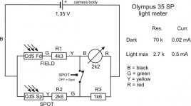
When I first took off the top of the camera and saw three resistors on the circuit board, I assumed it was a Wheatstone bridge design. Wrong assumption. The circuit can be seen in image 47 and it’s obvious it’s very voltage dependant. Of course, the idea was to put in a 1.55V silver cell. The problem is that the zinc-air cell that you all know costs almost the same, at least here where I live. Therefore, for the time being, for initial testing purposes I put in a 675 hearing aid cell (plus a small rubber ring made from a transparent hose to keep it properly in place. It’s inexpensive, it can be found anywhere. And my meter works fine (checked against my Gossen and other two TTL SLRs). At some point I’ll probably order the W*** cell.
Fresh alkaline batteries are a complete disaster: the meter reading is more than two stops off. Therefore useless.
Nevertheless, just for the fun of it, I’m considering replacing all the resistors with 5 kiloohms potentiometers – I should be able to precisely calibrate it to 1.55V then. But for the time being, in my situation, the cost / benefit ratio of this action is still doubtful.
Important points to note are that in complete darkness the circuit still takes 0.02 miliamps from your battery (right, almost nothing actually
) while the maximum current in blazing light barely reaches 0,5 miliamps. So it’s kind of an easy living for your battery anyway 
For some reason whatsoever, no matter what situation you put it into, my meter always reads a higher value for the “spot” reading. Never lower. If possible, please let me know about the behaviour of your meters. I suspect my CdS cells have some bridge contact between them. I mean on their actual board; you can see they are interconnected anyway afterwards.
Ninth part: the meter
When I first took off the top of the camera and saw three resistors on the circuit board, I assumed it was a Wheatstone bridge design. Wrong assumption. The circuit can be seen in image 47 and it’s obvious it’s very voltage dependant. Of course, the idea was to put in a 1.55V silver cell. The problem is that the zinc-air cell that you all know costs almost the same, at least here where I live. Therefore, for the time being, for initial testing purposes I put in a 675 hearing aid cell (plus a small rubber ring made from a transparent hose to keep it properly in place. It’s inexpensive, it can be found anywhere. And my meter works fine (checked against my Gossen and other two TTL SLRs). At some point I’ll probably order the W*** cell.
Fresh alkaline batteries are a complete disaster: the meter reading is more than two stops off. Therefore useless.
Nevertheless, just for the fun of it, I’m considering replacing all the resistors with 5 kiloohms potentiometers – I should be able to precisely calibrate it to 1.55V then. But for the time being, in my situation, the cost / benefit ratio of this action is still doubtful.
Important points to note are that in complete darkness the circuit still takes 0.02 miliamps from your battery (right, almost nothing actually
For some reason whatsoever, no matter what situation you put it into, my meter always reads a higher value for the “spot” reading. Never lower. If possible, please let me know about the behaviour of your meters. I suspect my CdS cells have some bridge contact between them. I mean on their actual board; you can see they are interconnected anyway afterwards.
Attachments
danieldumanescu
Member
Conclusion
This was not an easy task. As someone had written here on rangefinderforum before, it’s not a good camera to learn on if you haven’t done anything similar before. The purely mechanical AE system makes it as complicated as it gets. It’s a brilliant design (for 1969) but its myriad of parts also makes it prone to numerous faults. Not because it was not well built, but because it wears off in time. I’m absolutely sure no one at Olympus or Seiko was seriously wondering about how their mechanical systems would work after 40 years of (ab)use without any maintenance at all.
Disassembling everything may seem superfluous to some, but it’s the only method guaranteed to grant you a quiet sleep. You won’t be left wondering “maybe I should have also cleaned the xxx and the yyy?...” You’ll simply have the peace of mind that your camera is at its best, given its age and wear.
I was really happy when I found Brian’s tutorial. But I did not find any explicit material on this Seiko FLA shutter anywhere on the web. I’d be really happy if my experience helped other Olympus 35 SP enthusiasts out there.
I’ve just put a film in it – can’t wait to see the results.
P.S. 1) Ricoh 500G will follow at some point, when time allows.
P.S. 2) English is not my native language, so would you please excuse some potentially strange ways of putting it
Attachments
julio1fer
Well-known
Great thread, thanks for sharing your experience. I hope I'll never have to do this to my 35SP.
Please post some pictures from the camera after you get the test results!
oftheherd
Veteran
Impressive! Thanks for this. I will bookmark it in case mine needs help.
fullframe35
Member
Bravo! Did you ever post those pictures you mentioned at the end?
p.giannakis
Pan Giannakis
Great resource. Thanks for that.
charjohncarter
Veteran
Brave and impressive. Good luck with it.
Share:
-
This site uses cookies to help personalise content, tailor your experience and to keep you logged in if you register.
By continuing to use this site, you are consenting to our use of cookies.