Spyderman
Well-known
Hi,
I've been thinking about TTL metering for Zorki or FED for quite long. But just yesterday this idea suddenly came to my mind. I mean the circuit that I could use to make the TTL meter... And I'd like to hear opinions from those of you who understand electronics more than I do 😉
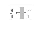
So this is the circuit:

The circuit uses one CdS cell for metering and 2 LEDs for display. There is one variable resistor for calibration. An IC with 2 comparators (click) (LM393N (click)) is used to compare the voltage of CdS and the variable resistor. When the first is greater then a LED will light. Notice the 2 comparators' inputs are inverted (once the CdS is connected to the inverting input and once to the non-inverting input, thus when the resistance is not equal one LED will always be turned on)
The CdS cell will be mounted in the camera body facing the shutter curtain with painted white (or grey) spot and it will receive the light reflected off the curtain.
The basic idea is that both LEDs will turn off (or on) when the resistance of the CdS and the variable resistor are equal. The resistance of the CdS can be controlled by aperture.
And if we assume that the shutter speed is 1/(film speed) we've got a "sunny f16" meter which turns both LEDs off when the aperture is correctly set.
(otherwise we would need to add one variable resistor that would change with shutter speed selected)
From purely electrical engineer's point of view - do you think it will work?
I've been thinking about TTL metering for Zorki or FED for quite long. But just yesterday this idea suddenly came to my mind. I mean the circuit that I could use to make the TTL meter... And I'd like to hear opinions from those of you who understand electronics more than I do 😉
So this is the circuit:
The circuit uses one CdS cell for metering and 2 LEDs for display. There is one variable resistor for calibration. An IC with 2 comparators (click) (LM393N (click)) is used to compare the voltage of CdS and the variable resistor. When the first is greater then a LED will light. Notice the 2 comparators' inputs are inverted (once the CdS is connected to the inverting input and once to the non-inverting input, thus when the resistance is not equal one LED will always be turned on)
The CdS cell will be mounted in the camera body facing the shutter curtain with painted white (or grey) spot and it will receive the light reflected off the curtain.
The basic idea is that both LEDs will turn off (or on) when the resistance of the CdS and the variable resistor are equal. The resistance of the CdS can be controlled by aperture.
And if we assume that the shutter speed is 1/(film speed) we've got a "sunny f16" meter which turns both LEDs off when the aperture is correctly set.
(otherwise we would need to add one variable resistor that would change with shutter speed selected)
From purely electrical engineer's point of view - do you think it will work?
Attachments
Last edited: