This Weekends Project

Local time
5:37 AM
Joined
Jun 6, 2009
Messages
3,147
Well, it's that time of the week, Friday night. At least it is Down Under. What are you up to this weekend?
I hope to get out to a local market and grab a couple of shots, but most of the weekend will probably be spent fettling this:

6890672477_832bbd5637_z.jpg


I purchased it ex-ebay late last year, where it was described in the listing as being in "good working order" a couple of months ago. Naturally, this meant that, when it arrived: the slow speeds were sticking; the self timer, doesn't, and, most seriously; the lens board is not moving evenly (it rocks slightly from side to side coming off infinity). Have I been down this road before? You better believe it! But it winds well enough and the shutter, although sticking on one second, seems to otherwise be OK.

The seller and I discussed the problems the camera suffers from and which differed from the item description. He offered to take the camera back, but I had decided I would rather keep it because, in spite of its faults, it has one massive point in its favour: both lenses are gorgeous. There is not a hint of the element separation so many Teles have been afflicted with over the years (Zeiss was an early adopter of synthetic bonding agents), and even the front coatings of both the lenses are like new.

On this basis I decided to work with its faults, and we agreed that the price would be adjusted. The refund more than paid for the purchase of a set of 0.35 Rolleinars, so I wound up with a Tele with some issues but with perfect lenses, and a set of Rolleinars, for about the same ebay price as a Tele with dodgy lens separation. I was satisfied with this and left some good feedback for him as, to his credit, we were able to negotiate this quite amicably.

Not surprisingly, the focussing issue is the most problematic. These parts are accessed from each side of the body. On the focussing side access is reasonably good—on the winding side—not so good! Much of the wind, film spacing and auto film sensing components reside in front of the wind side focus mechanism and this must be removed to reach it. It's one of the things that makes a Rolleiflex that much more complex than a Rolleicord.

First, in order to remove the winding side cover from the body the crank handle has to come off. Some of the repair texts recommend using a punch to drift it out. I don't like the idea of applying unnecessary force to a Rolleiflex. They're so beautifully and precisely built, so I'm not about to use a drift and a hammer (even a small one) to extract the pin that retains the handle. But what to do? Not possessing an extractor small enough to press it out, I thought about it for a bit, and eventually decided to try my drill press, which gathers dust out in my shed rarely used.

6890788727_f1795da460_z.jpg


An old 1.5 millimetre drill bit has been inserted into the chuck upside down to offer a flat surface to the end of the pin. It's not mounted particularly true, but for the purpose and force required is good enough! Note the block of wood next to the boss of the handle. The idea is to support the end of the wind shaft that the lever is fastened to, so that the pin can be pressed out very gently, but while transmitting minimum force into the shaft. Clearance between the side of the body and the drill chuck was tight—I would have been grateful for a longer bit—but it had just enough reach, and worked a treat as you can see below.

6891137127_eb915bb22c_z.jpg


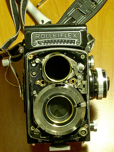
Of course, the front has to come off, in order to reach the shutter escapement and timer. First the screws that retain the bayonet rings must be removed, and the rings un-shipped. You can see two of the left side screws in the left side of the bayonet rings in the following shot.


6890942233_ce803b8673_z.jpg


There are three for each bayonet; the taking lens screw is easily seen at around two o'clock, the one for the viewing lens is just visible in the shadows at four o'clock. There are two more on the right side of the lenses, and also at the six and twelve o'clock positions for the taking and viewing lenses respectively.

The Tele is a little different to most Rolleis. The three screws which retain the bayonet for the viewing lens serve double duty. They also double as the locking screws for the viewing lens. Loosening or removing them enables the viewing lens to be unturned—and of course also permits the focus to be dialled in to that of the taking lens. This makes the Tele possibly the easiest Rollei model ever with which to match the lenses. Unlike the usual arrangement, the front does not need to come off it to loosen the lock screw for the viewing lens and adjust it. In the next shot, the viewing lens has been removed:

6890996549_beb045c159_z.jpg


After removing the locking rings for the shutter release and the PC connector terminal the front leatherette may be carefully prised back and the fixing screws for the front cover removed followed by the cover itself. The taking lens may then be removed presenting the front of lens board and shutter.

6890782265_802cec84ae_z.jpg


At twelve o'clock you'll see "500" in marker pen. This is the shutter setting ring, under which resides the profiled control ring (loosely, a type of cam) that positions the pins for the escapement gears and sets the speeds. The series of marks give a reference for all the shutter speeds down to bulb. Next to the (f/) "22" is the lever connected to the aperture control. Of course both these parts hook up with the setting wheels on the front of the camera via a small differential drive that manages the EV numbering (sigh...).

At each corner a small washer is lacquered into position quite securely. These are the shims that adjust the alignment of the front cover which will often be found somewhat wonky. I don't think this is an issue with this particular example, so the shims can stay where they are for the time being—adjustment of the front cover being entirely dependant on correct alignment of the lens board itself.

Speaking of this; there are a few issues that can throw this off, impact damage being the most obvious I suppose. But wear of the cam followers, old, dried out grease making things stick, and incorrect adjustment of the focus rails the board slides along can all need attention.

In this case, I'm hoping that cleaning the components and adjusting the followers and rails will get the board straight into the ballpark. The camera's not obviously bent, there is clearly excessive play or "float" on the wind side cams as it is lagging behind the focus side, and—having removed the wind side cover—I see just enough of the lens board and the rail to note some side thrust or "rocking" as the focus knob is gently rocked off and on infinity. Ie. excessive play between the board and the rail—hence I think (and hope!) it is just the focussing cams and rails that need wear adjusted out.

If I'm unlucky on the other hand, the lens board itself won't be sitting straight and will have to be removed for trial and error re-assembly to re-shim it true. The tolerance is 0.05 millimetres across the board, corner to corner diagonally. A dial gauge and surface plate are the go in assessing all of this.

You 2.8F owners get off lightly here; the F model was modified so that instead of shim adjustment four slotted collar and screw adjusters enable the parallelism to be set without actually taking the board off. On the plus side, the meter of the Tele Rolleiflex, being based on the E model is uncoupled, making it that much easier to deal with than the apparently complex coupled meter connections of the F. I say "apparently" because I haven't tackled an F yet.

With the wind side leatherette peeled off, removing two screws releases the cover disc for the wind shaft and the double exposure cam. After the five fixing screws for the cover are removed, the wind side cover may unshipped towards the top. Watch the loose washers underneath the holes for the cover screws, some of which are shaped to suit the body and are location specific! You'll then be presented with the beautiful Rollei wind and automatic spacing mechanism:

6890788731_1f30d29ef0_z.jpg


And there we leave it for tonight.
Next I'll get to discover the process of removing the winding gear, etc. to reach the focus system. More to follow...
Regards,
Brett
 
Last edited:
Keep it coming! Lots of great info.

Best as I've figured out, that kind of delay motion/rocking is from the small pressure bearing that pushes on the back side of the cams being out of adjustment. The bearing itself, the small reddish dot, sits at the end of a metal 'tube' on a flat plate held in place by two screws. There is a spring inside the tube. If the assembly isn't tight to the cam, the first bit of motion of the cams goes into compressing the spring, not actually moving the rails that ride on the cams.

Anything you can say about adjusting the focus system much appreciated. Taking that delay motion out is about the only thing I have been able to adjust on a Rollie, and I may be wrong about what is happening.

And it'd be great to see how you set up for checking alignment with a dial gauge. I float a gauge on a primitive clamp over a small slab of polished marble and slide the camera around underneath it, measuring on the film plane rails. but it's sloppy. Too bad I don't have access to a milling machine these days since it would make a nice jig.

Although a Minolta Autocord isn't as well-made as a Rolleiflex, there is one clear advantage: to remove the wind mechanism unit plate involves removing four screws and a couple of gears. That's it- then lift up. Another thing I haven't figured out yet- the proper order and way of sliding and lifting parts to get that plate out and in. I find it hard to imagine that Rollei would make access to such a basic thing as adjusting the focus mechanism so complex.

[The service manual I got from the web has a tolerance of 0.05mm across film plane, not 0.01mm. that's about 0.002 inch for the metrically challenged.]
 
You're spot on, Dan, I have the same manual and was relying on my memory when I wrote 0.01mm, it is 0.05mm, I'll correct that. I'm going to be in the same boat as you regarding the alignment, I'll be using a dial gauge mounted in a conventional mounting and either a sheet of plate glass or ground granite. A metal surface plate would be wonderful but it all costs... A jig would make the process easier without a doubt.

I think your comments regarding the bearings or followers for the cams are quite relevant here and I'd decided this is part of what is happening. I think there is also likely to be a little excess play between the carriage and the rails, at least on the wind side, as when the focus knob is adjusted, a little of that movement is being translated into up/down travel of the carriage (as opposed to in/out). It's not much but it's there I think. I'll obviously have a much better idea when I have removed the wind gear and can really see what is going on.
Regards,
Brett
 
Brett--great work and a beautiful camera!
Thanks for sharing your work.
But--isn't that a Canon strap?
Probably what made the focus mechanism run amok... :)
Thanks again and keep us posted...
Paul
 
Brett--great work and a beautiful camera!
Thanks for sharing your work.
But--isn't that a Canon strap?
Probably what made the focus mechanism run amok... :)
Thanks again and keep us posted...
Paul
Yes it is a Canon strap on my Tele Rollei. I'm sure there is a place in camera hell reserved especially for me...
Regards
Brett
 
This narrative has had one hugely beneficial outcome for me already. I'm NEVER, NEVER, EVER going to attempt anything like this myself!
 
Same for this little Kiwi, I will never try to repair a camera myself ... I was getting scared just reading your post Brett
 
Great job! Thanks for posting. I may decide to look inside my own Rolleiflex one day and will keep this link. Looking forward to your continued posts.

EDIT: I am a klutz at repairing, but you would be amazed at what you can do if you are careful and get correct tools. Then go carefully and document everything in writing and with photos. There is a good use for digital after all. :D
 
The first time I disassembled a Synchro-Compur, I *wished* I had drilled holes in my head instead. Especially when that one little spring went flying into the nether world.

(And the spring was actually *found* two days later, and the shutter chugs along nicely a year later. I can vouch for that repair working, but can't vouch for trepanation doing any good.)
 
Great job! Thanks for posting. I may decide to look inside my own Rolleiflex one day and will keep this link. Looking forward to your continued posts.

EDIT: I am a klutz at repairing, but you would be amazed at what you can do if you are careful and get correct tools. Then go carefully and document everything in writing and with photos. There is a good use for digital after all. :D

Yes, the first rule is not to damage anything. If you can stick to that, a lot of the rest comes down to: research; analysis; perseverance; patience--repeat ad nauseum. And you're right. The advent of digital imaging and the ability to effortlessly produce instant images of components and assemblies for reference purposes has, paradoxically, made it easier than ever to document correct step by step re-assembly later.

On the topic of research, I think it is worth mentioning that I've tried to assemble a small reference library of on-line and hard copy reference materials to assist with correct procedure, measurements and tolerances. I have a bookmarks folder with over a hundred links to various repair pages or sources of parts, acquired all the Tomosy repair volumes etc. as well as the factory Rollei TLR repair manual which is available for free on-line download from the nice people at the Classic Camera Repair Forum (a large 60 MB file, though--but it's free!). From ebay I sourced a CD with a copy of the factory Synchro Compur manual covering the shutters fitted cameras I use.

Possibly the best reference document I've acquired to date has been a copy of the National Camera Repair School manual for the 2.8F because it features actual photographs and more practical tips about the dis-assembly and re-assembly process. I bought that in hard copy on ebay, print quality was OK, too. A quick check shows it's presently being offered for USD $17.90 plus post by the same (US-based) seller I sourced mine from. It cost $16.90 postage to Australia, but if you're in the USA it's only $5.45 according to the listing, making it very good value and worth acquiring, IMHO, if you're thinking about doing any of your own Rollei repair work.

Apart from sharing the resources which are out there, a part of the reason I mention these is to support other owners who have a mechanical bent to have some belief in your own ability, and to promote a philosophy of doing your best work. In my case I've had absolutely no formal training in repairing cameras and just started tinkering with Japanese rangefinders, then a few Rolleicords, followed by a Bessamatic and some Contaflice (jumped into the deep end, with those two!).

To date I've managed to get several Rolleicords a two Bessamatics and a number of Contaflice working well (and still working well a couple of years later). I know my way around a Synchro Compur well enough to get them going again, if not to strip them down to all their component pieces. We all have to start somewhere, and the more you repair, the more you learn. The over riding message is that I didn't wake up Friday morning and decide to pull my Tele to bits—tackling a Rolleiflex is something I have been researching and slowly building up to, for quite some time now.

These old German cameras are in the first order of quality, and really were magnificently built indeed. If you tread carefully, so as not to break things, eventually, they will go back together correctly. As long as you've found yourself a decent example that has not been bashed, trashed, and thrashed: cleaning; lubrication; and adjustment; is generally all that is needed to make them work beautifully again. Assembling a decent reference library and doing your research first, rather than jumping in head first, helps a lot. But given patience and a methodical approach, there's no reason why anyone can't do this—the biggest challenge may be the time that's required—so many of us are time-poor these days. Perseverance really is key.
Sorry for such a wordy discourse.
Regards,
Brett
 
Last edited:
The first time I disassembled a Synchro-Compur, I *wished* I had drilled holes in my head instead. Especially when that one little spring went flying into the nether world.

(And the spring was actually *found* two days later, and the shutter chugs along nicely a year later. I can vouch for that repair working, but can't vouch for trepanation doing any good.)

Gosh, Dan, I can so relate to that. I've been there! And re: losing the spring. Reminds me of the time I dropped the set screw that holds the front lens group of a Voigtlander 135mm Super Dynarex f/4 Bessamatic/Ultramatic telephoto onto my floorboards. It must be about a millimetre wide, by two millimetres long? Finding that was an enjoyable couple of hours time spent—not! There are times I think I must be mad, but—when you've taken a really good shot with an old camera that wasn't working, that you've fixed—there is a certain amount of satisfaction involved, that really adds to the enjoyment of the process immensely which (hopefully) makes it all worthwhile.
Regards,
Brett
 
Not a lot of progress to report since the last photographsill health has intervened unfortunatelybut I'm now on the mend. I'm hoping to get back into it in earnest tomorrow, but I spent a little time tonight refreshing in my mind the procedures for stripping the wind side.

The manual I referred to previously suggested running the wind side of the camera through its paces with the cover off, to get an understanding for the way the mechanism works. This seemed like a worthwhile pursuit, so I loaded an old roll of Kodak Vericolor into the back of it to set the film spacing in motion and away I went. It's my first time inside a Rolleiflex (I've fixed a few Rolleicords) so a few extra reference photos may come in handy later, too.

First off here's a pointer (literally) to the film sensing adjuster. Although the Rollei film advance system is reliable, from the number of comments out there on the www it appears re-setting the sensor mechanism so it successfully finds the start of film is occasionally needed. The eccentric adjuster near the screwdriver tip is the means of setting the clearance through the sensing rollers so that the film counter trips correctly when rollers hit the film. It's come up in discussion on RFF occasionally--this is what it looks like. Rollei made a special gauge L-1949 for setting the rollers (this photo courtesy of the good Mr Kerensky will show you what it looks like if you're interested). But if you can remove the winding side cover, and have a couple of sets of feeler gauges, a scrap film, and a little patience, there's no reason why you shouldn't be able to adjust it yourself, if you're so inclined. If my memory is right, the rollers should feed the roll through continuously at .008" and trip the frame counter for the first film frame at .010". The factory manual I mentioned earlier should confirm this figure (in metric, of course!).

6915047469_0d7a15d88e_z.jpg


Speaking of scrap films...
After rapidly tiring of having to wind old, used rolls of 120 back to their start with a spare spool by hand, so that they could be re-used for testing Rolleiflex wind and spacing, I tried taping the loose ("exposed") end of the film down to the backing paper with a couple of strips of sticky tape to make it easier to manage.

It worked very well. By doing this, you can just wind your test film back and forth through a Rolleiflex from end to end, because two or three short strips of sticky overlaid across the end of the film will recreate the thickness of a piece of film tape well enough to fool a Flex into thinking you're at the start of a roll, not the end. It makes the testing process that much easier.
More to follow...
Regards,
Brett
 
Nice idea on the test rolls! I've re-wound so many rolls by hand, and now your idea makes that seem so silly.

That looks like the inside of the Rolleiflexes I've opened up. Except for the lever just to the left of the screwdriver, with its pivot point just above where the blade enters the handle. Haven't seen that before. Any chance that your camera does 220 film?

Anyway, a few things I have learned. first, the adjustment of the film sensor mechanism is not very touchy. The one time I did it, I scratched a reference mark and rotated the cam about 45 degrees in one direction. Not good. Back to the reference, 45 degrees the other direction- bingo! It's been working fine for fifty rolls since.

Photos, photos, photos. Different lighting, also. I have a desk lamp that I can shine directly or bounce up off the wall and ceiling.

Since you need to get to the focus mechanism, the main plate will be coming up. You will find one (or two??) corners that have no screws, only holes that mate with pins on the body. Lower right/front corner definitely. In that same corner, tucked behind the plate is a spring that.... well, let's see, maybe it connects the main plate and the lever running up the right side? Anyway, it's somewhat hidden and easy to miss until you have this spring hanging in space connected to nothing. Check it out before dismantling and look from the front, also- you can see it from the front through the opening where the shutter cocking mechanism moves.

And speaking of the lever running up the right side. See how at about 5 o'clock on the frame dial it travels through a slot in the main body? That frigging slot drove me nuts. It's just enough to make removing that part and/or sliding the main plate underneath it a real test. I am pretty certain that I missed something since I ended up needing t push and bow that lever. The metal was strong and it all worked again, but it is not desirable to need to flex and bow metal parts for this kind if mechanism.

Most of the pins and cams related to cocking the shutter and such go back into place pretty easily. At about 3 o'clock on your photo, slightly covered by the plastic plate over the wind mechanism, there are two smallish levers with various legs and such. Study these for a bit since this is actually one of the most important set of interactions in the mechanism. The shutter releasing moves one, allowing another to release and then affected by something else... well, details escape me, but I think if I remember the gist is that the lower one needs to be on the correct side of the upper one for things to work.

If you go inside the center mechanism under the wind crank, DO NOT grease or use much oil at all on the pawls of the ratchet mechanism you will find inside. Two pawls with light springs floating on a simple pivot each. I over-lubricated this first time and ended up with a wind lever that would free-wheel at random moments as both pawls got stuck un-engaged.

On one camera, the shutter would not cock at 1/500 even though I had not changed anything. So when you do testing, be certain to run through the speeds and be certain to do tests at closest focus also. Both can affect operation. There is an eccentric cam similar to the automat cam accessible which can be seen under the main plate to the left lower corner. This affects the travel of the shutter cocking mechanism. The goal is to have the shutter cock at all options, both speed and focus, but no more since it affects the ease of the whole mechanism.

The more I look at your photo, the more things look different around the winding area. Well, note where there appears to be any lubricant. I've seen very little signs of factory lube on most surfaces. The only place where I have found that grease is safe is the film spool drive gear and the one between it and the wind mechanism. On a Yashica-Mat, greasing this will eliminate most of the egg beater noise; on a Rolleiflex it reduces noise just a touch, so probably isn't worth risking.

Well, have fun! Not many springs to watch out for. A few shim washers scattered around so keep your eyes open for them. The odds are that things will slide back together quite nicely, the advantage of parts made well in the first place. The inside of a Yashica-Mat shows a similar mechanism but the finish level is of a different class.

(Just in case, you did note the flat spring for the film spool drive gear? It should be stuck to the side panel if you didn't see it when the panel came up.)
Hi Dan,
thanks for that information, you can't have too much. Yes the spring for the wind gear is safe and sound as it came off with the cover and is still on its seat.

Later Tele Rolleis were available with 120/220; this example is a Type 1 according to the serial number, and does not have the 120/220 switch. Looking at the images in the 2.8F manual, on that model, at least, if 120/220 capability is specified, there is a control lever fitted almost directly below the centre of the film counter dial which connects with the linkage for the external switch fitted to the outside of the wind cover. Frankly, I'm not sure off the top of my head what the other part you mentioned does do; I'll take another look at it, but it may become more clear, once the mounting plate for much of the mechanism has been removed and I can see how it relates.

Thanks for the tip about the one way clutch in the centre. I noticed yesterday, reading the 2.8F manual that it specifically mentions the need to keep lubricants away from it, so I spent a few minutes perusing the factory manual, and indeed, Rollei advised precisely the same treatment. So I'll be leaving it dry.

There is evidence of some old grease in and around some of the parts—this has not gone un-noticed—indeed, clues like these are important to note. The factory manual lists a number of different specific greases and oils; some are easy to second guess; others, frankly, are a mystery, and give little clue from their description as to what they were derived from. I'll have to address these issues when and if they arise. I won't be stripping the camera down to all component parts, the goal being to rectify specific problems—but having said that, I'll be attending to anything I find along the way.

It's good to hear some feedback about setting the sensor adjustment, as it has to come out to reach the focus system. You're spot on of course; marking the components for later re-assembly is always a good idea, and generally saves time by at least getting you in the ballpark, if not bang on. Happily I'm fairly well equipped with measuring equipment, and have feeler gauges, vernier calipers, dial gauge and micrometers. A couple of feeler gauges through the sensing rollers should enable me to get it right fairly quickly and I have several old films to test it with (testing with actual film being the final arbiter of correct adjustment IMHO).

Speaking of feeler gauges.
It crossed my mind that a cheap set of feeler gauges would be an easy, cheap source of shim stock. I might buy a set, if I find myself in need of any. They can be found for under $10, and a typical set has a convenient range of sizes that could be very useful for shimming the lens board or the front cover back to true. I thought wasn't a bad idea at all and wanted to mention it.
Regards,
Brett
 
Persuading the Light Meter Into Accuracy

Persuading the Light Meter Into Accuracy

Although I usually prefer to take an incident reading with a hand held light meter, and would not have minded if my Tele did not have a built in meter, it has one fitted, so I decided it would be nice if it worked correctly.

Being a Type 1 Tele Rolleiflex, the meter is like some of the E types. Ie. it is not coupled to shutter and aperture controls a la the F models, and has the high/low light selector switch by the top left corner of the meter cell housing/name plate to adjust the cell sensitivity and features a meter scale with dual light ranges.

When the camera arrived, the meter movement responded well to changes in light levels, so the cell was clearly producing some electrical output. But it was several stops off my comparative readings with a couple of light meters and some reliable SLRs. I initially experimented with the zero adjustment screw at the back of the meter assembly, but, although I was able to improve accuracy slightly, it was still out of range. The zero adjustment is properly set to a very small calibration mark on the meter scale, at the end of the scale closest to the front of the camera body, and is adjusted via an adjustment screw in the back of the meter housing which controls an eccentric.

Factory owners manuals for models fitted with this meter (which could be self-installed after purchase by owners) provide a diagram or two and some short instructions for adjusting the meter needle to the correct range as discussed above.

(It should be noted that when all is well, ensuring the needle is accurately zeroed, with no light whatsoever hitting the cell, is all that should be required to ensure maximum accuracy across the whole meter range. Sliding the needle across the range away from the calibration mark with the eccentric to try to restore a correct reading is therefore a bit of a bodge, which may or may not yield acceptable results, and even then, not necessarily across the whole measuring range).

Fifty-plus years after these cameras were made, it is either a matter of sourcing hard-to find OEM parts, or making the best of what you've got. Understanding that the current generated by these meter cells is extremely small, I decided to try cleaning the meter contacts, and those on the cell, to ensure minimum resistance to current flow, to see what, if any, improvement I could achieve.

The meter assembly is simplicity itself to detach. Back off the captive locking screw that holds the meter in the centre of the focus knob, and gently twist anti-clockwise to remove. When attached electrical contacts at the back of the meter depress matching contacts wired to the meter cell. Cleaning these with electrical cleaner made no noticeable difference I could see. On to the cell itself then...

Removal of the selenium cell is also straightforward. Special screws with no slots, but with small holes through the heads for a pin spanner retain the cell assembly/name plate to the camera body. Apparently, kits sold to owners for post-purchase meter installation included a tool for removing and attaching these; they do not have to be done up very tight, so, not having Rollei's original tool, I simply "borrowed" an appropriate size sewing needle from my wife's sewing kit, which did the job of extracting these admirably.

Once these are removed, the cell assembly simply detaches from the body. Electrical terminals to the wires connecting the cell to the meter are then exposed, the connectivity being achieved simply be the pressure of the cell retaining screws to the contact "pads".

Having dismantled the meter mechanism thus far I cleaned the exposed contacts with electrical contact cleaner, and gently dressed the contacts with a blunt jewellers screwdriver to remove any oxidised deposits.

Two small screws retain the backing plate of the meter cell to the "Rolleiflex" name plate that is its front and curiosity got the better of me at this point, so I removed the back of the cell to see if any other sources of electrical resistance were hiding within.

Here's a photo of the cell with the back removed. Apologies for the poor quality, taken with a cell phone (I don't own a working digital camera at present—I contemplated buying an X100 briefly last year, but bought a Tele Rollei instead!).


6937751087_cdc5b4701b_z.jpg


Not having stripped one of these before, I had assumed the high/low sensitivity of the meter would be set by a resistor circuit or two. So I was slightly surprised to find that, in fact, this is achieved completely mechanically, by means of a simple sliding "blind" that caps off part of the selenium cell in the high range, and exposes the entire cell for low range.

The following shot shows the cell stripped down to its basic components.

6937750951_53b5b86360_z.jpg


You can see the blind for the high/low range in the centre, which is connected the the selector switch by a simple cranked wire. To the right of this is the actual cell, next to which is the plastic cover for the cell that is essentially all that's visible when the unit is assembled on the camera.

Although you cannot really see it in the poor quality image, the selector switch has a spring loaded detent to keep it in position. The detent is a small bullet-shaped pin that is trapped in its socket on assembly.

Prudently, I feel, I elected to leave the cell riveted to the back of the housing. However as the back is simply a thin piece of pressed metal it is slightly flexible. After removing the clear external plastic cover I exposed top of the cell unit which has ten rectangular sectors as you can see in the above image. With some care I was able to very carefully slide a one millimetre screwdriver between this cover and the cell itself so I could carefully clean the contact strips to the actual cell.

The other point of interest is the small rectangular spacer with a round hole just visible on the bottom right. This fell out as the external cover was detached however it is shaped to fit into the second sector from the bottom of the cell cover and is trapped in place by the external cover.

It would appear its purpose is to calibrate the meter cell to a known value. Notwithstanding the poor quality of the above image you can just see that not all the lower sectors are the same size. One assumes that precise calibration of the cell output was achieved by the manufacturer (Gossen, who made the meter movement?) by the selection of the appropriate spacer of a certain size hole and/or the insertion to a certain sector of the cell. The National Camera Repair manual for the 2.8F advises that the meter movements and cells were supplied as a matched pair, presumably this also applied to the E models and that a technician calibrated each pair of cell and meter to specification. Interesting.

If you have ever wondered about the purpose of the small grub screw located directly beneath the high/low switch of your E or Tele, I can now reveal that. It secures the pin for the switch detent. Rather than having to try to juggle the switch, the blind and its linkage into the correct position, as well as the spring loaded detent pin for the switch, while you try to assemble the cell unit, the two halves can simply be mated with the blind and switch in place. After the back and the front of the unit have been combined, the pin for the switch detent may simply be pushed into the socket, followed by its spring, and the grub screw which secures them. Simplicity itself.

Happily, after the re-assembled cell assembly was attached to the body and the meter replaced in its bayonet, accuracy is greatly improved. I have not had an opportunity to do exhaustive testing yet but a half hour spent wandering around my property with the Tele, my Minolta meter and a recently-acquired and surprisingly accurate Zeiss Ikon Ikometer (hand held selenium meter) suggest it is now well in the ballpark. Further checking in a range of daylight light conditions will be needed for definitive results but preliminary checks suggest it is almost perfect. Hopefully, another win!

More to follow...
Brett
 
Last edited:
Back
Top Bottom