wolves3012
Veteran
As I will explain shortly, by means of some internal photos of the mechanism, this isn't quite an accurate description. The RF image does not move at all, it is fixed. Only the VF image moves. In using the camera, there is something of an illusion of a moving RF image, probably because it's what an RF-user would expect and the RF image is a relatively small portion of the total frame in view.The real star of the show, however, is the rangefinder. I've never seen anything like it. It's not a standard ghost-image spot; instead, the rangefinder "spot" is a solid part of the viewfinder, and you have to find and join vertical lines that dissect the boundary between the RF and VF panes. It's not very RF-like - more like a split-prism SLR finder. This design may seem weird, but it actually allows the VF to be brighter and clearer than many cameras. But where it really shines is that as you focus both the RF and the VF images move - in opposition to each other, of course. This is where the claims of parallax correction come from; the framelines (50/85/135 - black, clear, and nice and unobtrusive) remain still while the actual view changes, allowing the limits of the VF to act as a parallax-corrected 35mm frame.
Wulfthari
Well-known
As I will explain shortly, by means of some internal photos of the mechanism, this isn't quite an accurate description. The RF image does not move at all, it is fixed. Only the VF image moves. In using the camera, there is something of an illusion of a moving RF image, probably because it's what an RF-user would expect and the RF image is a relatively small portion of the total frame in view.
Yes, I checked your pictures, the RF mechanism is crazy...who said the Soviets were just good at copying western designs? However, I'm eager to try the camera with the lenses I currently have with me and another type of film, my pics with BW400CN looks a little washed out.

wolves3012
Veteran
Here goes on the Leningrad's RF system! First, an overall view with the top cover removed:
It's a little hard to see much in there, it's pretty complicated. There are 8 optical parts. Things to note in the photo: the large block on the right hides the RF mirror and there's a collimating lens underneath it nearer to the visible brass ring on its left end. The silver block near the upper left is a prism, not unlike an SLR's pentaprism, except this one is narrower and rests on its side. Here is another view from a slightly different angle:
Next, a view of the optical path through the elements. I've outlined the optical prisms in purple and used a red line to show the mirrored faces of the two mirrors. The blue lines show the positions of lenses (although there is also one in the eyepiece tube) and the green lines mark out 2 small screens. Note that the left-hand mirror is the one that rotates in response to the focus sensor tip, this makes the VF image move and not the RF image. I never found the framelines but I think they must be on the rear of the front prism-block that sits just behind the VF window. You can see the moving mirror's pivot between two small screws, near to the small gear visible on the lower left.
Here is a close-up of the prism, the small RF-image screen is clearly visible on the right hand end:
Now to that block hiding the RF mirror, this is a close-up showing the adjustment screws. There are three pairs of screws, shown boxed in red:
Notice the crazing to the surface, this is not crazed old paint, unfortunately - it's the actual alloy on this example! Despite a LOT of care, when I removed the top right large screw, the corner of the block crumbled away and I was left with a major problem. Here is a picture of the finished repair:
This required a metal-filled epoxy and a great deal of patience to re-fashion the required shape, drill the screw-hole and then drill a countersink hole!
In the next post I'll detail some tips on how to adjust the RF successfully, how to take off and (crucially) re-install the top-plate cover.

It's a little hard to see much in there, it's pretty complicated. There are 8 optical parts. Things to note in the photo: the large block on the right hides the RF mirror and there's a collimating lens underneath it nearer to the visible brass ring on its left end. The silver block near the upper left is a prism, not unlike an SLR's pentaprism, except this one is narrower and rests on its side. Here is another view from a slightly different angle:

Next, a view of the optical path through the elements. I've outlined the optical prisms in purple and used a red line to show the mirrored faces of the two mirrors. The blue lines show the positions of lenses (although there is also one in the eyepiece tube) and the green lines mark out 2 small screens. Note that the left-hand mirror is the one that rotates in response to the focus sensor tip, this makes the VF image move and not the RF image. I never found the framelines but I think they must be on the rear of the front prism-block that sits just behind the VF window. You can see the moving mirror's pivot between two small screws, near to the small gear visible on the lower left.

Here is a close-up of the prism, the small RF-image screen is clearly visible on the right hand end:

Now to that block hiding the RF mirror, this is a close-up showing the adjustment screws. There are three pairs of screws, shown boxed in red:

Notice the crazing to the surface, this is not crazed old paint, unfortunately - it's the actual alloy on this example! Despite a LOT of care, when I removed the top right large screw, the corner of the block crumbled away and I was left with a major problem. Here is a picture of the finished repair:

This required a metal-filled epoxy and a great deal of patience to re-fashion the required shape, drill the screw-hole and then drill a countersink hole!
In the next post I'll detail some tips on how to adjust the RF successfully, how to take off and (crucially) re-install the top-plate cover.
wolves3012
Veteran
Ok, tips on what to do and what NOT to do if you need to adjust the RF on your Leningrad. Note that the horizontal alignment should normally be adjustable satisfactorily by means of the sensor-tip angle and infinity adjustment and this would not require removing the top-plate at all. Adjusting it internally is not for the faint-hearted so you do so entirely at your own risk!
Removing the top cover:
Unload the spring tension as far as you possibly can. You can "help" the shutter to re-cock by removing the back and turning the film spool in its normal direction and reduce the tension much further that way. Set the flash-sync dial to "0" and make sure it stays there since it likes to turn with the winder. Also, note the selected shutter speed.
Loosen the two grub-screws in the speed-selector dial's rim. Don't take them out if you can help it, just enough to remove the dial is all you need. Pull up on the rewind knob, as if you were going to rewind a film. Remove the eyepiece tube by unscrewing it. Take out the 5 screws around the top plate. Now carefully lift the whole top-plate off, keeping it "square" as you do so. As you lift, you'll hear the remaining spring tension go ping - don't worry! Don't lose the spring coupler as you remove the top-plate, it's the black split-shaft piece that will probably fall out of the middle of the spring-motor. Re-fit the eyepiece tube else you won't be able to see much.
Freeing-off the adjusters:
Referring to the photos in the post above, identify the three pairs of adjuster screws. The RF mirror sits on a triangular plate underneath the large block just behind the RF window. These screws allow the mirror to be moved in all three dimensions.
First, the do nots. DO NOT dive in and simply unscrew ANY of the screws yet! First, understand how they work and also understand that they are locked in place with shellac (probably) and they are (likely) seized as well.
The triangular plate holding the RF mirror has three threaded holes, corresponding to the larger screw-heads visible. The three small grub-screws are threaded only into the top alloy piece and poke through the back of it. This creates three points on which the mirror-plate sits. If you loosen the larger screw and tighten its corresponding grub-screw, you move that corner of the mirror-plate downwards - or if you loosen the grub-screw and tighten the larger screw it moves upwards. Hence, any of the three corners can be moved vertically, tilting the mirror-plate in any desired direction. Additionally, the larger screws are recessed into "slots", loosening all three allows some slight rotation of the mirror in a horizontal plane.
Scrape away what you can see of the shellac, then dissolve the rest by soaking it off with tissue or cotton buds soaked in ethanol. Make sure you NEVER press down hard on the screw-heads, ONLY turn them with minimal down-pressure. Now you'll need some penetrating oil and a lot of patience. Soak all 6 screws with a drop of penetrating oil and leave it for at least a day. Keep adding oil as needed from now on. Try releasing each screw in turn, just a fraction. If it moves at all, re-tighten it slightly and then loosen it some more, a little at a time. The screws are steel and they thread into alloy of a very brittle nature and they are VERY likely to be seized from years of being in there. Patience and repeating the tighten-loosen pattern should free them up. Don't undo all the screws at once, work only on one at a time until they are all quite free.
Adjusting the RF:
Next, determine which way the RF image is "off". If it slopes, you'll need to tilt the mirror-plate using the right-hand pair of adjusters. If it's too high or too low use the front ones. Move the mirror-plate in the same direction as the "problem" (e.g. move it up if the image is too high).
Be aware that if you've got this far, you'll soon discover that the adjusters are very sensitive. Even a few degrees has a noticeable shift in the RF image, so will need a lot of patience to hit the exact spot. Whichever pair of screws you are working on, always loosen one then tighten the other by about the same angle and do NOT do any of them over-tight, the alloy is liable to fall apart!
Once you have the RF adjusted correctly to your satisfaction, apply some form of locking to all of the screws (nail-varnish, a small dab of paint etc).
Re-fitting the top-plate:
Re-fitting the top-plate is quite tricky. Remove the eyepiece tube again first. Inside the top-plate, you will see what looks like a black gear-wheel, close to the centre of the spring-drive. It's actually the frame-counter wheel and it is spring-loaded towards the centre of the drive. Carefully, re-insert the drive coupler shaft, making sure the split engages properly on the spring. Take a piece of sewing cotton thread and make a half-loop around the frame-counter pivot screw (yes, really, you can just about do that). Pass the free ends over the edge of the top-plate. Push the frame-counter wheel against its spring, away from the spring coupler shaft. Pull the thread ends tightly and wrap them several times around the counter advance button. This keeps the counter wheel out of the way for now.
Take a look at the slot where the spring coupler engages on the camera body and note the angle it is at. Turn the winder knob on the top-plate until the coupler position matches. Now double-check the flash-sync has not been moved off "0".
Lower the top-plate back into position, checking carefully that the spring coupler will line up and the flash-sync coupler does too. The top-plate should sit right down until the screws can be re-inserted. If it does not appear to do so, double check that the couplers aren't in the way and that the frame counter hasn't moved. Once the top is sat down properly, unwrap the thread and pull it out by one end. Re-fit the 5 screws and re-fit the speed selector dial to the set speed you noted and re-fit eyepiece tube. Check the spring-drive motor works properly. I suggest you only turn it a couple of turns initially, just to feel that the tension is building as expected. If it goes ping you failed to re-engage the coupler properly (although you cannot easily re-fit the top-plate if that's the case)
Job done!
Roger Hicks
Veteran
Thanks for visual confirmation of what I had always heard: that the chassis (zinc alloy? pot metal?) was grievously susceptible to crumbling.
They're fun -- when and if they work. I've had a couple: still have one. But as I am now more interested in taking pictures than in trying (literally) crumbly cameras...
Cheers,
R.
They're fun -- when and if they work. I've had a couple: still have one. But as I am now more interested in taking pictures than in trying (literally) crumbly cameras...
Cheers,
R.
wolves3012
Veteran
Roger, actually the chassis of that example looks much like any regular Zorki or FED, so I don't think it's in great danger of falling apart without provocation. The crazed-alloy metal appears to be the (extensive and complex) RF mechanics casting. Obviously this is one example but if the metal there is typical, I'd love to know what percentage of castings went in the bin when they tried to do the machining work.
nhchen
Nathan
Make sure you NEVER press down hard on the screw-heads, ONLY turn them with minimal down-pressure.
Haha, wish I had known this for before I tried to adjust the rangefinder on mine. Where your's crumbled on the corner, the whole piece holding the prism and the lens of the rangefinder image crumbled into four pieces. Apart from the weak alloy, I think the other problem is that there is no support underneath that prism holding it up (the rangefinder connection to the lens is underneath it) which makes it extremely fragile if you press on it.
I was never able to put it back together again..oh well...
regards,
nathan
wolves3012
Veteran
Interesting to see that the poor alloy may be typical rather than an isolated example then.
Wulfthari
Well-known
It surprises me how persistent was the Soviet Government in giving all the most complicated projects to GOMZ/Lomo,a relatively minor company with little experience in high quality manufacture (unlike Kiev Arsenal and KMZ, for instance).
10 years after the Leningrad the Soviet MOD ordered Lomo to proceeed with the most complicated mission they had ever given to a camera manufacture: to build a professional grade system SLR to replace....well the Nikon F2 that the Soviet journalists were using in the first 70s and they had to import at dear price. The result was the Almaz family and probably the greatest failure of the Soviet photographic industry ever..for more or less the same reasons the Leningrad is a tricky camera.

Fotohuis
Well-known
I will keep it on a Zorki 4(K), Z-6 or FED-3 or 5B.
The repair of a Zorki including new curtains for Eur. 15,- was already a big fix.
Fortunately not by myself but a well trained Zorki/FED doctor.
Here the right sync time switch repair.
And this is the result with a J-8:
Fomapan 200 in Xtol 1+1.
or in flash mode:
BTW, sometimes you get them in the original Sovjet boxes, very funny.
The repair of a Zorki including new curtains for Eur. 15,- was already a big fix.

Fortunately not by myself but a well trained Zorki/FED doctor.
Here the right sync time switch repair.
And this is the result with a J-8:

Fomapan 200 in Xtol 1+1.
or in flash mode:

BTW, sometimes you get them in the original Sovjet boxes, very funny.

carbo73
Well-known
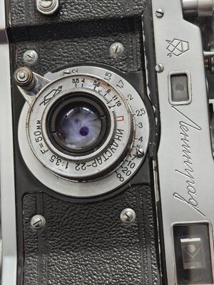
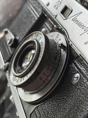
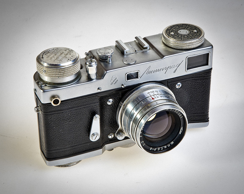
That's my Leningrad, a fully working and quite unique example, due to it's dedication hand-made inscription. I think my camera was made by GOMZ in 1958 or 59.
First we talk about the inscription, in cursive Cyrillic and that I have translated as I could thanks to the internet:
"1972р
П/П Садовникову ВП
от офицеров -
сослуживцев
о. Сахалин
май"
That is: "In 1972, for P./P. Sadovnikov V.P., from his fellow officers, Sakhalin Island, May."
It is obviously a camera given as a present to a Soviet army officer by his colleagues, all from the garrison of Sakhalin Island in northern Japan. The Leningrad was one of the highest quality cameras in the USSR, although this was manufactured about 12 years before 1972. Therefore it was a gift of great prestige. The owner is V.P. Sadovnikov, clearly a Soviet officer himself.
Other elements not so clear are the beginning and the end of the text. This ends with the word "May", which I can only interpret as the present being given on May 1, which is quite logical in the Soviet world and even more so in the army, as it was a day of parades and celebrations. The most difficult to see the meaning of is the abbreviation П / П, that is, P.P. Although I have not been able to confirm this, it may refer to the Soviet rank of Lieutenant Colonel, as this was a podpolkovnik (подполко́вник), and pp seems like a logical abbreviation.
The interesting question here is that I have come across a Soviet official who corresponds to this name and surname: Valentin Pavlovich Sadovnikov (Валентин Павлович Садовников). This is a major-general born in 1938. In 1979 he comanded the 42th Armoured Division, and between 1983 and 1985 he commanded the 8th Armored Army!! Then he retired. It seems bold, but the surname and patronymic fully coincide with the person receiving this camera. Could it be that this officer was a lieutenant colonel in Sakhalin in 1972 and that 11 years later he had promoted to general and commanded an armored corps? Ah ...
As I said before, the shutter works wonderfully well, and although the rangefinder is a bit displaced (I have managed to correct the vertical misalignment, but not the horizontal, that miniature screw is so hard to reach without disassembly...), it could take nice pictures. I'm quite used to older, no-rangefinder cameras (Kodaks Folding Pockets etc), so focusing as a guess is not so difficult.
Some examples:
First we talk about the inscription, in cursive Cyrillic and that I have translated as I could thanks to the internet:
"1972р
П/П Садовникову ВП
от офицеров -
сослуживцев
о. Сахалин
май"
That is: "In 1972, for P./P. Sadovnikov V.P., from his fellow officers, Sakhalin Island, May."
It is obviously a camera given as a present to a Soviet army officer by his colleagues, all from the garrison of Sakhalin Island in northern Japan. The Leningrad was one of the highest quality cameras in the USSR, although this was manufactured about 12 years before 1972. Therefore it was a gift of great prestige. The owner is V.P. Sadovnikov, clearly a Soviet officer himself.
Other elements not so clear are the beginning and the end of the text. This ends with the word "May", which I can only interpret as the present being given on May 1, which is quite logical in the Soviet world and even more so in the army, as it was a day of parades and celebrations. The most difficult to see the meaning of is the abbreviation П / П, that is, P.P. Although I have not been able to confirm this, it may refer to the Soviet rank of Lieutenant Colonel, as this was a podpolkovnik (подполко́вник), and pp seems like a logical abbreviation.
The interesting question here is that I have come across a Soviet official who corresponds to this name and surname: Valentin Pavlovich Sadovnikov (Валентин Павлович Садовников). This is a major-general born in 1938. In 1979 he comanded the 42th Armoured Division, and between 1983 and 1985 he commanded the 8th Armored Army!! Then he retired. It seems bold, but the surname and patronymic fully coincide with the person receiving this camera. Could it be that this officer was a lieutenant colonel in Sakhalin in 1972 and that 11 years later he had promoted to general and commanded an armored corps? Ah ...


As I said before, the shutter works wonderfully well, and although the rangefinder is a bit displaced (I have managed to correct the vertical misalignment, but not the horizontal, that miniature screw is so hard to reach without disassembly...), it could take nice pictures. I'm quite used to older, no-rangefinder cameras (Kodaks Folding Pockets etc), so focusing as a guess is not so difficult.
Some examples:


Ko.Fe.
Lenses 35/21 Gears 46/20
Май is May and nothing else.
It feels sorry if this camera one of the highest quality from USSR. Despite their better than nothing prestige, they were ditched as soon as cameras which were made where soviet tanks could not make, stay became available.
Working (somewhat) Leningrad is very rare occurrence these days.
It feels sorry if this camera one of the highest quality from USSR. Despite their better than nothing prestige, they were ditched as soon as cameras which were made where soviet tanks could not make, stay became available.
Working (somewhat) Leningrad is very rare occurrence these days.
Share:
-
This site uses cookies to help personalise content, tailor your experience and to keep you logged in if you register.
By continuing to use this site, you are consenting to our use of cookies.