
R
ruben
Guest
My Kiev shooter, i.e. the main one which I have been using several months ago, is at my hospital quite a long time. It started with the winding fork, giving me too long spaces between frames, then it continued with the story of the eyepiece, upon which i noticed i am having tilted images, and then i had problems with the rangefinder mechanism.
Upon all these troubles and fixings, I come to the conclusion that my preference of the later models 4am, is not the most suitable for fixings. It is not due exactly to the amount of problems but the small parts, being of quite low quality and not upstanding much fiddling.
Ok, now for what i have learned and can share.
The worm shape - source of troubles
it happens that the worm arm has to light depressions, one at the begining and the other after aprox 1cm. This 1cm makes a slightly lower height at the center, while higher at the begining or the end.
But from several worms i have seen, the depression is not equal in all of them, and these differences have tremendous micronic implications on the overall extension size of each worm.
Consequently if you have a too much depressed worm, your overall alignment work of the range finder coincidence will be harder. The more "straight" the worm, the more easy to align the rangefinder.
But it is not as easy as it sounds, since the worm must have some level of depression at the middle, since it starts at a high compensator basis, then it must lower to avoid collusion with the prism holders, and then rise again to match the lever moving the worm forwards and backwards - the very range-finding operation.
At the end of a full day of work i am done for the short distances, tomorrow morning infinity eureka or crisis.
Tilted images at the yellow patch.
If you happen to notice that vertical lines show slightly diagonal at your yellow patch, Maizenberg refers us to the rectangular plano convex glass (rectangular dome shaped) of the rangefinder window. Unfortunately he doesn's say what to look for or what to do, and this type of reference is not to my best taste. Not with Maizenberg, not elsewhere.
But upon trying and trying I found that the story is to elevate one of the extreme sides, of the plano convex piece, via one or two small washers we have to provide from our side stock.
The winding and rewinding friction principle of the Contax/Kiev
Noel has already been teaching us that what moves the film when we wind, is not the winding fork and spool, but the sprockets. This is comfirmed by Maizenberg, and although I have not memorized all the KSS, I am sure it is there too. Fine.
But what is the function then of the winding fork? Should it be free and allow the sprockets to do the job or what ?
I am fully convinced that here is the source of frame spacing problems, since the sprockets give a consequent amount of turns corresponding to one frame per cocking.
Since in my Kiev 4am the fork is slightly different shaped, and there is a fixed spool, etc, i.e. I am not learning from a classical Kiev, i have been having trouble until I realized the principle is the same for all Kievs including my 4am, and that big amount of washers I found was absolutely unnecessary.
The winding fork has a highly important task both in the correct winding and rewinding. The "task" at the re-winding is passive, of course, but a misaligned winding fork will further dis-align at the re-winding. And therefore will intensify frame spacing problems.
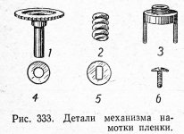
For a quick and dirty explanation (or rather theory for discussion) I will be using the attached draw from Maizenberg's Russian edition book.
Here we see first (No 1) the tooth wheel. This wheel engages the whole winding mechanism found at the top casting, while the cylinder axis penetrates a bigger cylindrical tunnel leading to the winding spool. Only the lower end of this axis protrudes and engages the fork.
But this draw is highly misleading in the most crucial issue. The lower end is not circular at all but filed at two extremes, enabling part No 5 to engage. Part 5 is a strong spacer, that once engaged to the end of the axis may enable you to turn the whole thing by turning the spacer. And vice versa.
This is highly important because when all the parts at the draw are assembled, you cannot see if Part 5 is correctly engaged or not. Here the trap. If it is not correctly engaged the whole assembly will not properly work, without you necessarily noticing it but when it is too late. But now, lets skip this issue in order to advance, and we will return later.
Let's suppose that we install the wheel 1, then the fork (Part 3), then Part 5 and finally the screw (6). The problem is that the gears, at the top casting, advance forwards but not backwards, meaning for our assembly that it will wind but brake the re-winding, due to the wheel being stopped together with all winding gears.
Therefore the Contax designers decided to make the winding and rewinding movement of the FORK, not exactly by the positive movement of wheels, but by FRICTION POWER. Friction power will advance the fork once pushed by the wheel 1, and friction power will enable the re-winding, once we transmit force through the rewinding button, SKIPING OVER THE FACT THAT AT THE REWINDING, WHEEL 1 REMAINS STILL.
This friction is produced by spring No 2, inserted around the axis of wheel 1.
True, due to the filed end of the axis of wheel 1, and spacer 5, the winding movement is not only by friction but also due to the movement of the wheel 1, but the pressing force of the spring 2 is what retains the spacer 5 in place, and avoids the screw 6 to disengage at the rewinding.
Washer No 4, whose place is between the fork 3 and spacer 5, enables easier counter clockwise friction of spacer 5 and the fork.
This theory I am presenting answers as well to the question of how much tension should we have at our fork. Provided spacer 5 is correctly in place, we should have stronger enough tension to provide us a positive movement of the fork, parallel to the winding movement of the sprockets, AND NO LESS THAN THAT, and enough not too-much tension to enable easy re-winding, while keeping spacer 5 in place.
Now, how do we install spacer 5 in place, while during the installation screw 6 head hides the orientation of the spacer and the filed protrusion of the axis of wheel 1?
I have had some hard time with it, so I prefer to leave this question open to further contributions of other friends here. I can say that I marked the matching extremes of spacer 5 and the matching position of wheel1, marked too at its top. But this is just a start of a beginer. Conoussieurs: duty calls.
Cheers,
Ruben
Upon all these troubles and fixings, I come to the conclusion that my preference of the later models 4am, is not the most suitable for fixings. It is not due exactly to the amount of problems but the small parts, being of quite low quality and not upstanding much fiddling.
Ok, now for what i have learned and can share.
The worm shape - source of troubles
it happens that the worm arm has to light depressions, one at the begining and the other after aprox 1cm. This 1cm makes a slightly lower height at the center, while higher at the begining or the end.
But from several worms i have seen, the depression is not equal in all of them, and these differences have tremendous micronic implications on the overall extension size of each worm.
Consequently if you have a too much depressed worm, your overall alignment work of the range finder coincidence will be harder. The more "straight" the worm, the more easy to align the rangefinder.
But it is not as easy as it sounds, since the worm must have some level of depression at the middle, since it starts at a high compensator basis, then it must lower to avoid collusion with the prism holders, and then rise again to match the lever moving the worm forwards and backwards - the very range-finding operation.
At the end of a full day of work i am done for the short distances, tomorrow morning infinity eureka or crisis.
Tilted images at the yellow patch.
If you happen to notice that vertical lines show slightly diagonal at your yellow patch, Maizenberg refers us to the rectangular plano convex glass (rectangular dome shaped) of the rangefinder window. Unfortunately he doesn's say what to look for or what to do, and this type of reference is not to my best taste. Not with Maizenberg, not elsewhere.
But upon trying and trying I found that the story is to elevate one of the extreme sides, of the plano convex piece, via one or two small washers we have to provide from our side stock.
The winding and rewinding friction principle of the Contax/Kiev
Noel has already been teaching us that what moves the film when we wind, is not the winding fork and spool, but the sprockets. This is comfirmed by Maizenberg, and although I have not memorized all the KSS, I am sure it is there too. Fine.
But what is the function then of the winding fork? Should it be free and allow the sprockets to do the job or what ?
I am fully convinced that here is the source of frame spacing problems, since the sprockets give a consequent amount of turns corresponding to one frame per cocking.
Since in my Kiev 4am the fork is slightly different shaped, and there is a fixed spool, etc, i.e. I am not learning from a classical Kiev, i have been having trouble until I realized the principle is the same for all Kievs including my 4am, and that big amount of washers I found was absolutely unnecessary.
The winding fork has a highly important task both in the correct winding and rewinding. The "task" at the re-winding is passive, of course, but a misaligned winding fork will further dis-align at the re-winding. And therefore will intensify frame spacing problems.
For a quick and dirty explanation (or rather theory for discussion) I will be using the attached draw from Maizenberg's Russian edition book.
Here we see first (No 1) the tooth wheel. This wheel engages the whole winding mechanism found at the top casting, while the cylinder axis penetrates a bigger cylindrical tunnel leading to the winding spool. Only the lower end of this axis protrudes and engages the fork.
But this draw is highly misleading in the most crucial issue. The lower end is not circular at all but filed at two extremes, enabling part No 5 to engage. Part 5 is a strong spacer, that once engaged to the end of the axis may enable you to turn the whole thing by turning the spacer. And vice versa.
This is highly important because when all the parts at the draw are assembled, you cannot see if Part 5 is correctly engaged or not. Here the trap. If it is not correctly engaged the whole assembly will not properly work, without you necessarily noticing it but when it is too late. But now, lets skip this issue in order to advance, and we will return later.
Let's suppose that we install the wheel 1, then the fork (Part 3), then Part 5 and finally the screw (6). The problem is that the gears, at the top casting, advance forwards but not backwards, meaning for our assembly that it will wind but brake the re-winding, due to the wheel being stopped together with all winding gears.
Therefore the Contax designers decided to make the winding and rewinding movement of the FORK, not exactly by the positive movement of wheels, but by FRICTION POWER. Friction power will advance the fork once pushed by the wheel 1, and friction power will enable the re-winding, once we transmit force through the rewinding button, SKIPING OVER THE FACT THAT AT THE REWINDING, WHEEL 1 REMAINS STILL.
This friction is produced by spring No 2, inserted around the axis of wheel 1.
True, due to the filed end of the axis of wheel 1, and spacer 5, the winding movement is not only by friction but also due to the movement of the wheel 1, but the pressing force of the spring 2 is what retains the spacer 5 in place, and avoids the screw 6 to disengage at the rewinding.
Washer No 4, whose place is between the fork 3 and spacer 5, enables easier counter clockwise friction of spacer 5 and the fork.
This theory I am presenting answers as well to the question of how much tension should we have at our fork. Provided spacer 5 is correctly in place, we should have stronger enough tension to provide us a positive movement of the fork, parallel to the winding movement of the sprockets, AND NO LESS THAN THAT, and enough not too-much tension to enable easy re-winding, while keeping spacer 5 in place.
Now, how do we install spacer 5 in place, while during the installation screw 6 head hides the orientation of the spacer and the filed protrusion of the axis of wheel 1?
I have had some hard time with it, so I prefer to leave this question open to further contributions of other friends here. I can say that I marked the matching extremes of spacer 5 and the matching position of wheel1, marked too at its top. But this is just a start of a beginer. Conoussieurs: duty calls.
Cheers,
Ruben
Attachments
Last edited by a moderator: