esearing
Established
Fascinating! Congratulations on your work, we are all cheering you on.
I do have a concern about the 2 motor design. Will they be able to be kept in sync over time? What happens when they fall out of registration, will there be some kind of adjustment a non technical user can make?
Pherdinand
the snow must go on
does it use any position encoder of the moving head to keep track of where it is, or do you solely rely on the movement of the motors (in this case the rigidity of the transmission and even the frame might be problematic)
quejai
Established
Fascinating! Congratulations on your work, we are all cheering you on.
I do have a concern about the 2 motor design. Will they be able to be kept in sync over time? What happens when they fall out of registration, will there be some kind of adjustment a non technical user can make?
Thank you!
That would be a considerable risk if we used normal motors. Instead, stepper motors are used, which allow very predictable operation.
However, now and then it will probably be good to confirm alignment; this can be done automatically where the camera will measure light intensity as the two modules move in different directions. By measuring changing light intensity in the upper imaging module (the 'camera') as the two modules move, the scanner can confirm that it is still in proper alignment.
There are also going to be limit switches for another level of position feedback, but overall I'm pretty sure that going out of alignment / registration would be quite unusual, and also very easy to detect and fix automatically by the scanning software.
Perhaps each time new film is loaded, or the scanner is started, a double-check routine will happen where alignment of everything is checked? I'm still developing the algorithms for the software, and this is what I've been thinking about
quejai
Established
does it use any position encoder of the moving head to keep track of where it is, or do you solely rely on the movement of the motors (in this case the rigidity of the transmission and even the frame might be problematic)
No position encoder is used, instead the signals sent to the stepper motors are recorded and used to estimate the position of the scanning head to around +/- 1mm. We can do this thanks to the properties of stepper motors, this is why they're so good and widely used in robotics.
This accuracy is easily good enough, as software can do the final level of tile stitching by getting things into absolutely perfect alignment.
However, limit switches at the ends of the inside of the scanner will be used as a way to calibrate the starting position of each of the moving modules.
Jockos
Well-known
If you would add a user accessible compartment the bottom of the chassis to slide in some ballast to reduce vibrations - it could save a lot on international shipping rates.
I bet most of us can get lead BBs or similar easily locally!
The Nikon 9000 for comparison, is over 9 kg in weight!
I bet most of us can get lead BBs or similar easily locally!
The Nikon 9000 for comparison, is over 9 kg in weight!
quejai
Established
If you would add a user accessible compartment the bottom of the chassis to slide in some ballast to reduce vibrations - it could save a lot on international shipping rates.
I bet most of us can get lead BBs or similar easily locally!
The Nikon 9000 for comparison, is over 9 kg in weight!
A user-installable ballast would be very convenient indeed. I'll do some experiments to see if a ballast is necessary, and what size is ideal.
To clarify for other readers: As the blue parts in the diagram need to move back and forth quite fast, there's the risk that some vibrations or shaking might be experienced. There are a couple of ways to reduce this effect; such as selecting a slower scan speed in software, by very slightly changing the speed to avoid resonances, by adding weights to the scanner's frame (Jockos's idea), or by having some kind of shock absorption system in the case - rubber pads, for example. I think that a combination of all of these approaches will be used in the end, but we'll know more detail about this after further experiments.
astro8
Well-known
That aluminium extrusion is very rigid. I don't see any problems there. Where shaking could occur is down to the type of rollers and rails and the weight of the sensor and light source. Linear rail would be ideal, as it is very rigid but it can be rather expensive.
Lighter plotters, printers, cutters and laser cutters use rather simple rollers and rails as the heads are quite light... The laser cutters can really fly because the heads are so light. Heavier versions use linear rail as the cutting/printing/laser heads can be rather heavy.
I'd love to see this scanner with linear rail. What a machine that would be!
I'm now wondering what decent Chinese versions are available for an economical price....hmm.
The stepper motors are the best choice from my perspective. They are louder but fairly trouble free, no encoders to worry about and to keep costs down. As you say, it could do a homing routine on each start up. The more I see of your design, the more I'm warming to it.
I'm no expert, just a curious and interested observer.
quejai
Established
astro8:
Thanks for the interest! I had a similar thought train to you a couple of months ago, and then I realised - the aluminium frame could *be* the linear rail. And so that's what the current design is going for, as it saves size/cost/weight, and noise too. I was using conventional steel linear rail on the first prototype last year, and it was noisier than I was expecting.
The imaging modules each have four wheels, two on each side, which enables it to roll up and down the aluminium frame. The wheels engage horizontally on the inner side of the frame. The sensor and light source are both going to be fairly light weight, I think around 250 grams each.
Interestingly, the ball bearing assemblies of these wheels are the most likely things to wear out of the whole scanner. And guess what? They're essentially off the shelf items, which means that future repairs and maintenance will be much easier than otherwise.
Attachments
Tijmendal
Young photog
Amazing! This all looks very promising. Great to finally see some pictures. Can't wait to see some samples. Keep up the great work!
Tijmendal
Young photog
Amazing! This all looks very promising. Great to finally see some pictures. Can't wait to see some samples. Keep up the great work!
dseelig
David
A stack loader for slides that does not jam can clean kodachrome as well as regular e 6 and balck and white it can clean
Erland
Member
I am really enjoying this project! I also agree that stepper motors is the way to go. We have it all over our machines ( I work with production printers) and their precision and durability is very hard to beat. The home positions sensors could be either switches or light barriers, and both have their strengths and weaknesses, though generally light barriers have longer lifetime from my own experience.
another thing you should consider is the wear of the belts. Even 3M's belts do expand in time, and that will change the output, and this could be enough to make the parallel plane between the sensor and light source to begin fine, and at the end of the film be out of sync.
Also, bearings in those belt tensions rollers are also under stress. Consider xxxxZZ bearings since they allow more vibrations (though I think you already know this).
But I gotta say, Damn I am impressed! Looking forward to see some output of this very intriguing machine!
Kind regards
Marcus!
MikeL
Go Fish
another thing you should consider is the wear of the belts. Even 3M's belts do expand in time, and that will change the output, and this could be enough to make the parallel plane between the sensor and light source to begin fine, and at the end of the film be out of sync.
Nice efforts quejai!
I have similar thoughts as Erland. If the optical modules are light, you might think about a single belt (rather than one that loops around a bearing, doubling its length) that the steppers rest against, and the steppers move with the optical modules. The advantage is no bearings to wear out and you remove/minimize the tension-stretching of the belt.
I don't have Erland's experience at this scale, but I used to do research in a 80m long by 3m wide flume that had a measurement cart on top. I could place the measurement laser (altimitry) on a sand grain, run it down 50m, and have it return to the same sand grain. After a lot of trials the best design used a very stiff tape with ridges that ran between gears. They had to develop a system to get power to the cart+motor since the motors were not fixed and moved with the cart, but it was worth it given the precision gains.
Your equipment may be light and this may not matter. The cart we had was heavy with gear.
aoresteen
Well-known
Very hard survey to answer. I could not find what is the max size negative that the scanner will handle. If it is limited to 35mm I would not buy it.
I need a scanner that will do 70mm film edge to edge to edge and 17cm long. That will handle my 70mm 6x6/6x7 negatives as well as my 120/220 film 645,6x6,6x7,6x8,6x9, 6x12,6x17, and 2.25 x 3.25 sheet film.
For that with good resolution I'd pay $2000.
Good luck with your project.
I need a scanner that will do 70mm film edge to edge to edge and 17cm long. That will handle my 70mm 6x6/6x7 negatives as well as my 120/220 film 645,6x6,6x7,6x8,6x9, 6x12,6x17, and 2.25 x 3.25 sheet film.
For that with good resolution I'd pay $2000.
Good luck with your project.
jpk
Newbie
pgk
Well-known
There are a couple of ways to reduce this effect; such as ..... or by having some kind of shock absorption system in the case - rubber pads, for example. I think that a combination of all of these approaches will be used in the end, but we'll know more detail about this after further experiments.
https://en.wikipedia.org/wiki/Sorbothane
Asprine
Member
The anticipation is killing me 
How is it going?
You must have tackled at least 10 problems, and of course got some new ones in return.
How is it going?
You must have tackled at least 10 problems, and of course got some new ones in return.
quejai
Established
The anticipation is killing me
How is it going?
You must have tackled at least 10 problems, and of course got some new ones in return.
It's going pretty well, but no major news to report as of yet. As usual the final parts order is taking up much of my time, and once it's out of the way I'll write up a schedule / timeline that should be significantly more reliable than my earlier projections. Then I'll be able to move on from the mechanical stuff and focus on electronics, programming and testing.
Long story short, I'm doing this final parts order in stages. The first stage is to make prototypes of each module that are bulky and ugly, but perfectly functional and infinitely adjustable. Once adjustments have been made to account for any deviations between the theoretical and the ideal positions of things, such as lens elements for Kohler alignment in the light source, measurements will be made. Then the design will be updated, another order will be made, and hopefully then we will be totally done with these parts. (but only this first stage will be needed to make the first test scan!)
Just so you know, the blue parts of the diagram will need to be able to make three passes of the length of the scanner each second at maximum speed. At that rate, it's extremely important to carefully position the center of mass of each moving part, while still keeping things small and lightweight, and at the same time minimising aerodynamic effects caused by this fast motion, and avoiding wobbling, etc etc. Anyway I've got a design that can get around all these constraints, I just need the measurements from the first stage of this parts order.
I'll make an update here of when the order for that first set of parts has been submitted, as this order seems to defy any sort of forecast schedule. However earlier on today I finished what I consider to be the hardest module, the light source.
Regarding suggestions made recently:
Sound absorbing pad - looks good! That link is a material that has the right properties.
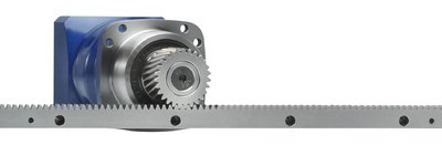
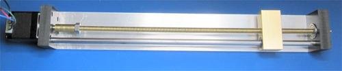
Avoiding belt - that's what I did in the first prototype last year, using a screw linear motion thing, and it was a bit too slow. If the off-the-shelf belt needs to be replaced by the user each year or so in a worst case heavy-usage scenario, I think that's acceptable for the speed advantages it brings. However if the belt is especially problematic I will spend more time investigating screws and racks.
Super accurate measurement cart - interesting! Intuitively my response would be to say that having the stepper motor moving along with the optical modules would add excessive inertia, which would be bad, but earlier on in the week I was playing around with some very lightweight drone motors, so this is a possibility. However I'm going to stick with the current approach for the prototype, but I'll keep this in mind.
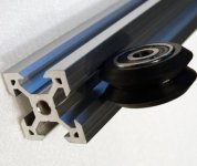
Floppy belt - That does sound inconvenient, but as it is the wheels which keep the image plane perpendicular to the lens axis, even in a worst case scenario all that would happen is that the 'tiles' have less regular gaps than normal, which means that the software tile stitching would take several milliseconds longer than before. I don't think this is too much of a worry, but I'll keep an eye out for possible expansion and sagging of the belt, which is something that should be minimised in any case.
Tension tolerant ball bearings - I actually didn't know this, thanks for making me realise that not all ball bearing assemblies are the same. Fortunately I lucked out, and the bearings I have now are designed for high tension loads, but when I make other orders for bearings in the future I'll make sure to be aware of whether they can deal with the tension properly.
Asprine
Member
It's going pretty well, but no major news to report as of yet...
Thanks for the update and insights, very much a priciated!
athos
Still like film
Resolution... 6000 REAL ppi
Medium format capability
Color
Reliability
Adjustable resolution: speed ratio
Cost, $1000-$2000
Ease / ergonomics of use / software experience
Clear documentation of operational methods
Speed
Medium format capability
Color
Reliability
Adjustable resolution: speed ratio
Cost, $1000-$2000
Ease / ergonomics of use / software experience
Clear documentation of operational methods
Speed
Share:
-
This site uses cookies to help personalise content, tailor your experience and to keep you logged in if you register.
By continuing to use this site, you are consenting to our use of cookies.